A vertical cooling furnace and its cooling method

A cooling furnace, vertical technology, applied in the direction of furnaces, furnace components, lighting and heating equipment, etc., can solve the problems of low gas-solid heat transfer efficiency, insufficient contact between sinter particles and cooling gas, etc., and achieve the degree of dense particle accumulation Improve and improve the efficiency of gas-solid heat exchange and avoid the effect of pipeline effect

Active Publication Date: 2022-02-25
NORTHEASTERN UNIV LIAONING
View PDF8 Cites 0 Cited by
  • Summary
  • Abstract
  • Description
  • Claims
  • Application Information

AI Technical Summary

Problems solved by technology

[0005] In order to solve the technical problems of insufficient contact between sinter particles and cooling gas in the vertical cooling furnace and low gas-solid heat exchange efficiency in the prior art, the present invention provides a vertical cooling furnace and its cooling method, which has The furnace chamber structure of the Venturi effect changes the flow channel width of the material to be cooled and the cooling gas, thereby changing the gas flow rate and particle flow rate in the furnace chamber, increasing the gas-solid heat transfer coefficient in the furnace chamber, and improving the gas-solid exchange rate. heat to improve recovery of waste heat

Method used


Image

  • A vertical cooling furnace and its cooling method
  • A vertical cooling furnace and its cooling method
  • A vertical cooling furnace and its cooling method

Examples


Embodiment 1

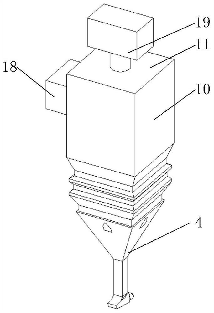
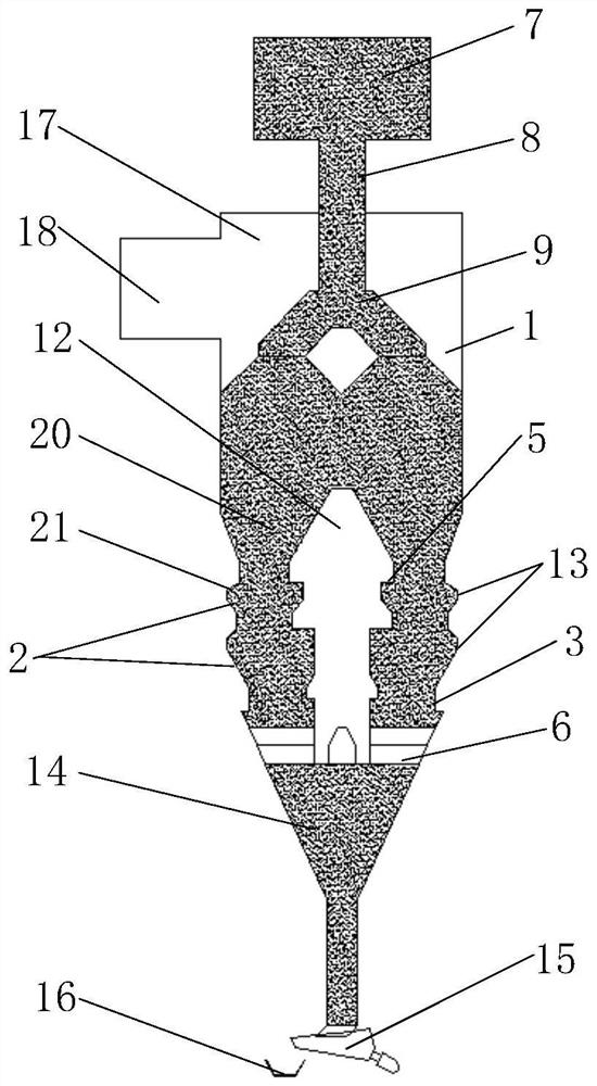
[0073] Such as Figure 1 to Figure 5 As shown, a vertical cooling furnace, the material to be cooled is sintered ore, along the flow direction of the material, sequentially includes:

[0074] Feeding unit 19, the feeding unit 19 includes a buffer bin 7, a material guide pipe 8 and a feeding pipe 9 connected in sequence, the feeding pipe 9 extends into the furnace chamber 1, and the feeding unit 19 is arranged above the furnace chamber 1 , used to load high-temperature sintered ore into the furnace cavity 1, wherein the buffer bin 7 is used to receive the high-temperature sintered ore transported by the loading trolley, and the material guide pipe 8 is arranged at the bottom of the buffer bin 7 to connect the buffer bin 7 and the unloading Pipe 9, in this embodiment, the feeding pipe 9 is an inverted V-shaped structure, and in actual use, different forms of material distribution devices such as central feeding and side feeding can also be used;

[0075] Furnace cavity 1, the m...

Embodiment 2

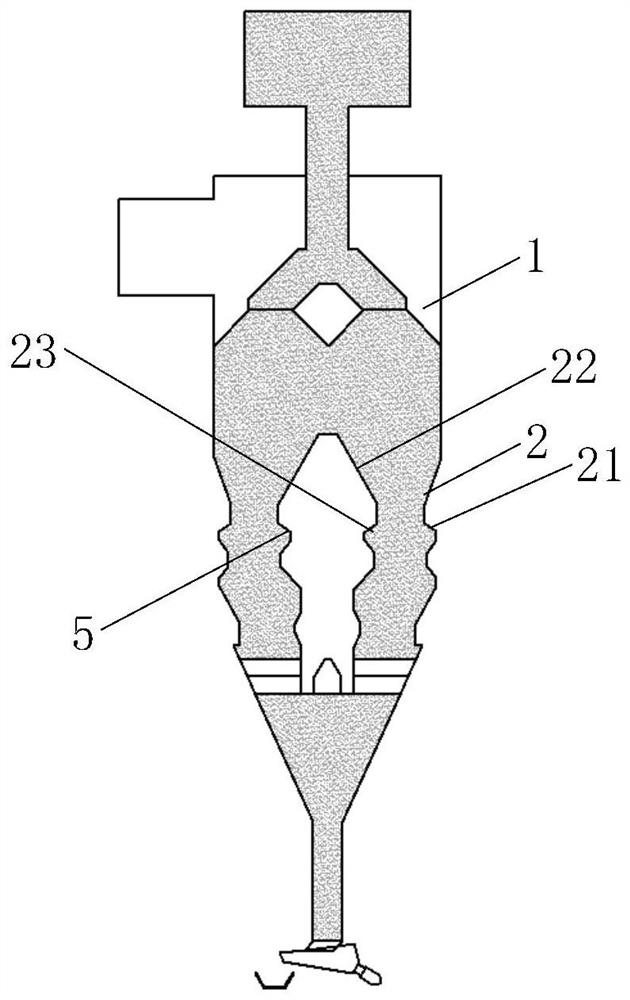
[0093] Such as Figure 6 to Figure 13 As shown, this embodiment provides a vertical cooling furnace and a cooling method thereof. The structure of this embodiment is basically the same as that of Embodiment 1, except for the following differences: two sets of depressions are provided, and two layers of the central air cap 12 are provided. The annular air outlet 5, and in this embodiment, the connection section 3 of the uppermost recessed part is arranged coaxially with the furnace cavity 1 .


PUM


Abstract

A vertical cooling furnace and a cooling method thereof belong to the technical field of waste heat recovery process equipment in the metallurgical industry. The vertical cooling furnace, along the material flow direction, sequentially includes: a feeding unit; a furnace chamber, through which the material to be cooled flowing in through the feeding unit enters into the furnace chamber, and a hot air duct is arranged on the furnace chamber, and the hot air duct communicates with the The furnace cavity and the outside; the air supply unit is arranged in the furnace cavity, the air supply unit is suitable for connecting with the air supply unit, and the air supply unit is provided with at least one air outlet; along the height direction, at least a part of the inner wall of the furnace cavity is provided with a depression The concave part extends toward the air supply unit; the cooling method of the vertical cooling furnace includes the following steps: feeding, cooling by heat exchange for the first time, cooling by heat exchange for the second time, and discharging. The vertical cooling furnace and its cooling method can change the gas flow rate and particle flow rate in the furnace cavity, so that the gas-solid heat transfer coefficient in the furnace cavity can be improved, thereby improving the gas-solid heat transfer and increasing the recovery rate of waste heat.

Description

technical field [0001] The invention relates to the technical field of waste heat recovery process equipment in the metallurgical industry, in particular to a vertical cooling furnace and a cooling method thereof. Background technique [0002] In the iron and steel production process, the energy consumption of the sintering process is second only to ironmaking, and is the second largest energy-consuming process, accounting for about 10%-20% of the total energy consumption of steelmaking. The sintering process contains huge waste heat resources. The waste heat resources carried by 1 ton of sintered ore can reach 0.94-1.02GJ, and the sensible heat of sintered ore accounts for about 50% of the total waste heat resources in the sintering process. Therefore, the efficient recovery of sintered ore sensible heat It is one of the important means for iron and steel enterprises to realize energy saving and consumption reduction. Most domestic large iron and steel companies use waste ...

Claims


Application Information

Patent Timeline
Patent Type & Authority Patents(China)
IPC IPC(8): F27D15/02
CPCF27D15/0286
Inventor 祁腾飞李海峰
Owner NORTHEASTERN UNIV LIAONING
Why Eureka
Try Eureka