Numerical control laser cutting control system for power battery pole piece

A numerical control laser and power battery technology, applied in laser welding equipment, manufacturing tools, welding equipment and other directions, can solve the problems of high equipment cost, polluted cutting working environment, and high laser heat, achieve increased operating efficiency, avoid high temperature deformation, avoid The effect of circulating countercurrent

Inactive Publication Date: 2021-07-02
JINAN G WEIKE SCI & TECH
View PDF6 Cites 3 Cited by
  • Summary
  • Abstract
  • Description
  • Claims
  • Application Information

AI Technical Summary

Problems solved by technology

[0004] The purpose of the present invention is to provide a power battery pole piece numerical control laser cutting control system to solve the problem that the metal chips in the numerical control laser cutting process are generally relatively small, and it is easy to form irregular sputtering melts on the cutting metal surface, causing power failure. The surface of the battery pole piece is rough, and the debris sputtered in the air will become smoke and dust, polluting the cutting work environment, and the heat emitted by the laser is very high, it is troublesome to cool down the laser head, the heat emitted by it is not easy to reuse, and the energy utilization rate remains to be seen. Improvement, the height of the laser is adjusted by the mechanical arm, and the problem of high equipment cost

Method used


Image

  • Numerical control laser cutting control system for power battery pole piece
  • Numerical control laser cutting control system for power battery pole piece
  • Numerical control laser cutting control system for power battery pole piece

Examples


Embodiment

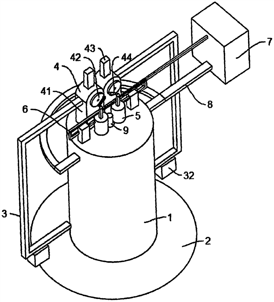
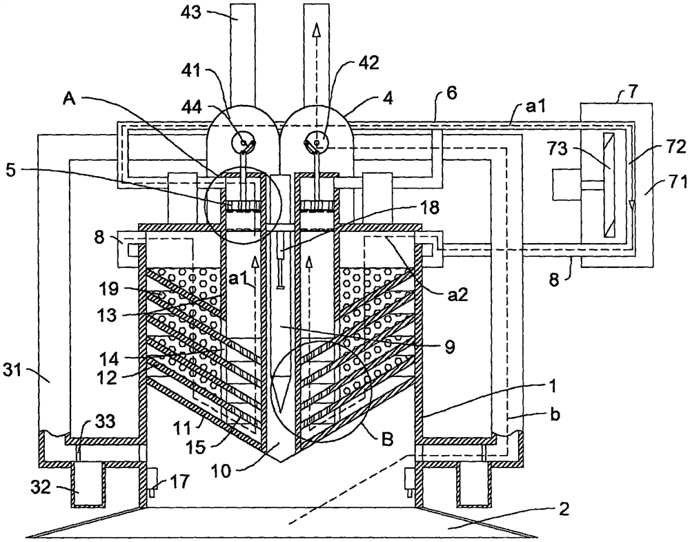
[0029] Such as Figure 1-5 As shown, in the embodiment of the present invention, a power battery pole piece numerical control laser cutting control system includes a cylindrical sleeve 1, and also includes: a conical dust collection cover 2 connected to the bottom of the cylindrical sleeve 1; a dust suction pipeline 3. Symmetrically connected to the outer side of the lower half of the cylindrical sleeve 1, wherein the dust suction pipeline 3 is connected to the blast structure 4; the pneumatic piston cylinder 5 is connected to the coaxial position of the blast structure 4; the steam pipe 6 is connected to the pneumatic piston On the cylinder 5, the steam pipe 6 is connected to the air-cooled water-cooled equipment 7; the liquid pipe 8 is connected to the air-cooled water-cooled equipment 7; the high-pressure laser gun 9 is installed in the center of the cylindrical sleeve 1, and the inside of the cylindrical sleeve 1 is equipped with heat dissipation structure.

[0030] The h...


PUM


Abstract

The invention relates to the field of numerical control laser cutting control equipment, in particular to a numerical control laser cutting control system for a power battery pole piece. The system comprises a cylindrical sleeve and further comprises a conical dust hood, dust collection pipelines, a pneumatic piston cylinder, a steam pipe, a liquid pipe and a high-pressure laser gun, wherein the conical dust hood is connected to the bottom of the cylindrical sleeve; the dust collection pipelines are symmetrically connected to the outer side of the lower half section of the cylindrical sleeve, and the dust collection pipelines are connected with an air blowing structure; the pneumatic piston cylinder is connected to the coaxial position of the air blowing structure; the steam pipe is connected to the pneumatic piston cylinder, and the steam pipe is connected with air-cooling and water-cooling equipment; the liquid pipe is connected to the air-cooling and water-cooling equipment; and the high-pressure laser gun is installed at the center position of the cylindrical sleeve, and a heat dissipation structure is arranged inside the cylindrical sleeve. According to the device, real-time cooling in the laser cutting process can be achieved, the suction-force-variable smoke dust absorption effect is achieved, kinetic energy generated by vaporization of a cooling agent is converted to provide mechanical energy for dust collection, heat emitted by laser is effectively utilized, energy is saved, and laser distance measurement is automatically adjusted, so that the system is convenient and practical.

Description

technical field [0001] The invention relates to the field of numerically controlled laser cutting control equipment, in particular to a numerically controlled laser cutting control system for power battery pole pieces. Background technique [0002] The power battery pole piece is an important part of the battery. It is divided into a positive pole piece and a negative pole piece. The positive pole piece is coated with a slurry containing lithium ions on aluminum platinum, and the negative pole piece is coated with a slurry whose main component is graphite on copper platinum. During production, the positive and negative electrodes are separated by separator paper, and then rolled into the desired shape. The tabs are the leads of the positive and negative electrodes, which are respectively connected to the positive and negative electrodes. The materials include nickel strips, aluminum strips, etc. . The thickness of the power battery pole piece is generally relatively thin, b...

Claims


Application Information

Patent Timeline
Patent Type & Authority Applications(China)
IPC IPC(8): B23K26/38B23K26/142B23K26/70
CPCB23K26/38B23K26/142B23K26/703
Inventor 蒋习锋孟超超
Owner JINAN G WEIKE SCI & TECH
Why Eureka
Try Eureka