
Harmless treatment device for sludge

A technology of harmless treatment and sludge, applied in biological sludge treatment, water/sludge/sewage treatment, sludge treatment through temperature control, etc. The effect of high mud utilization rate and convenient composting treatment

Inactive Publication Date: 2021-07-13
李玲
View PDF6 Cites 1 Cited by
  • Summary
  • Abstract
  • Description
  • Claims
  • Application Information

AI Technical Summary

Problems solved by technology

[0005] Aiming at the deficiencies of the prior art, the present invention provides a sludge harmless treatment device, mainly to solve the problem that it is not easy to discharge the sludge when sterilizing and drying the sludge

Method used


Image

  • Harmless treatment device for sludge
  • Harmless treatment device for sludge
  • Harmless treatment device for sludge

Examples


Embodiment 1

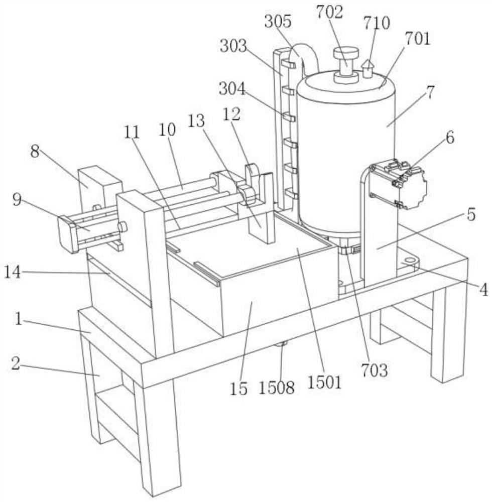
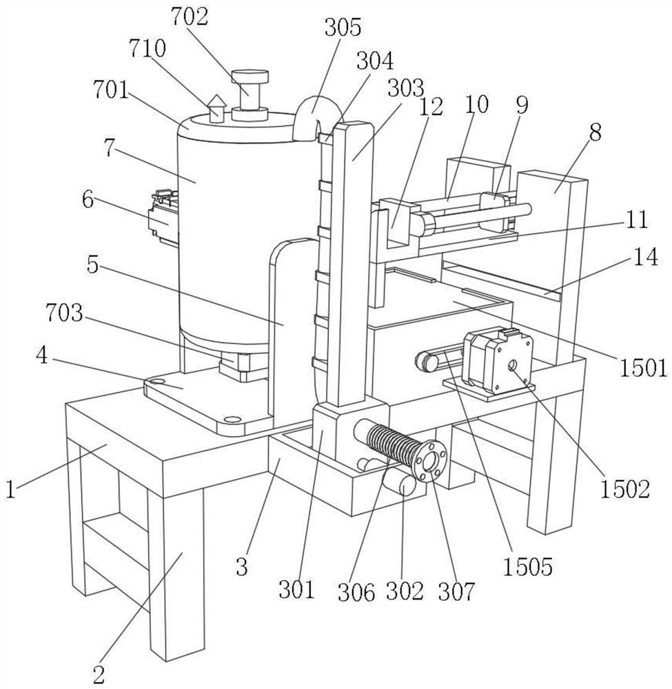
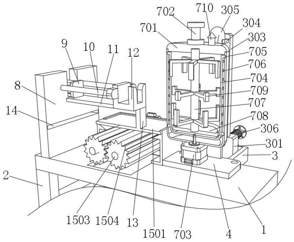
[0033] refer to Figure 1-Figure 5, a sludge harmless treatment device, comprising a bottom plate 1, a support frame 2 is fixed on the bottom of the bottom plate 1 by bolts, a feed adjustment mechanism is provided on one side of the bottom plate 1, and a fixed plate 4 is fixed on the upper surface of the bottom plate 1 by bolts , and the upper surface of the fixed plate 4 is fixed with two fixed frames 5 by bolts, and one side of the fixed frame 5 is fixed with a servo motor 6 by bolts, and a sludge treatment mechanism is connected between the two fixed frames 5, and the sludge treatment mechanism The setting can kill harmful substances and insect eggs in the sludge by heating at high temperature, and can also evaporate excess water in the sludge. The sludge treatment mechanism includes the outer cylinder 7 and the inner cylinder 704, and one side of the inner cylinder 704 is integrally formed There is a sliding ring 705, and the sliding ring 705 is slidingly connected with th...

Embodiment 2

[0037] refer to Figure 6-Figure 7 , a sludge harmless treatment device, one side of the support frame 2 is fixed with a second slideway 1602 by bolts, and one side of the second slideway 1602 is slidably connected with a slide rail 1601, and the slide rails 1601 are all fixed by bolts There is the same fermentation tank 16, and the fermentation tank 16 that can be pulled is set, which abandons the disadvantages of the traditional fermentation tank being inconvenient to move, and is more convenient for post-composting treatment. It has certain innovations and improves the efficiency of composting to a large extent. In order to improve the efficiency of sludge harmless treatment, one side of the fermentation tank 16 is fixed with a hinge by bolts, and the other side of the hinge is fixed with a discharge door 1603 by bolts.

[0038] The present invention also includes a method of fermenting sludge into fertilizer, the specific method is as follows:

[0039] S1: Adding bacteria...


PUM


Abstract

The invention relates to the technical field of sludge treatment, and discloses a sludge harmless treatment device, which comprises a bottom plate, wherein a supporting frame is fixedly connected to the bottom of the bottom plate, a feeding adjusting mechanism is arranged on one side of the bottom plate, a fixing plate is fixedly connected to one side of the upper surface of the bottom plate, two fixing frames are fixedly connected to the upper surface of the fixing plate, one side of each fixing frame is fixedly connected with a servo motor, a sludge treatment mechanism is rotatably connected between the two fixing frames, the sludge treatment mechanism comprises an outer cylinder and an inner cylinder, a sliding ring is integrally formed on one side of the inner cylinder, the sliding ring is movably connected with the inner wall of the outer cylinder, a top cover is clamped to the top of the outer cylinder, and a clamping shaft is fixedly connected to the upper surface of the top cover. According to the invention, discharging and cleaning are convenient, the discharging speed of solid sludge is guaranteed to a great extent, certain creativity is achieved, the sludge harmless treatment effect is improved, the dried and sterilized sludge can be subjected to smashing pretreatment, and the composting effect is improved.

Description

technical field [0001] The invention relates to the technical field of sludge treatment, in particular to a sludge harmless treatment device. Background technique [0002] As we all know, municipal sludge refers to the solid waste generated during the treatment of urban domestic sewage and industrial wastewater. Sludge contains toxic and harmful substances such as heavy metals, pathogenic bacteria, and parasite eggs. With the development of urban industry and economy, the amount of sludge has increased sharply. Improper disposal may cause serious damage to the ecological environment and human health. How to treat sewage The use of sludge becomes the top priority. There are many existing sludge treatment methods. The harmless methods include anaerobic digestion, aerobic digestion, sludge composting, heat treatment, biological leaching, etc., using sludge composting The most cost-effective method is the method with a relatively high utilization rate. [0003] At present, mos...

Claims


Application Information

Patent Timeline
Patent Type & Authority Applications(China)
IPC IPC(8): C02F11/18C02F11/13B02C4/08C02F11/02C05F17/70C05F17/40C05F17/914
CPCC02F11/004C02F11/18C02F11/13B02C4/08C02F11/02C05F17/70C05F17/40C05F17/914C02F2303/04Y02W30/40
Inventor 李玲
Owner 李玲
Learn More