High-power alloy foil resistor and manufacturing method

A manufacturing method and alloy foil technology, applied in the direction of resistance manufacturing, non-adjustable metal resistors, resistors, etc., can solve the problems of accelerating product failure and increasing heat accumulation, so as to achieve a smooth path for heat diffusion, improve heat overflow, The effect of ensuring firmness

Active Publication Date: 2021-07-13
NANJING SART SCI & TECH DEV
View PDF4 Cites 4 Cited by
  • Summary
  • Abstract
  • Description
  • Claims
  • Application Information

AI Technical Summary

Problems solved by technology

In addition, the production process of resistors needs to adjust the resistance value of the product by adjusting the cross-sectional area of ​​the middle area of ​​the resistance element. The reduction of the cross-sectional area of ​​the middle area will also increase the heat accumulation in this area and accelerate product failure.

Method used


Image

  • High-power alloy foil resistor and manufacturing method
  • High-power alloy foil resistor and manufacturing method
  • High-power alloy foil resistor and manufacturing method

Examples


Embodiment 1

[0032] This embodiment is an embodiment of a resistor.

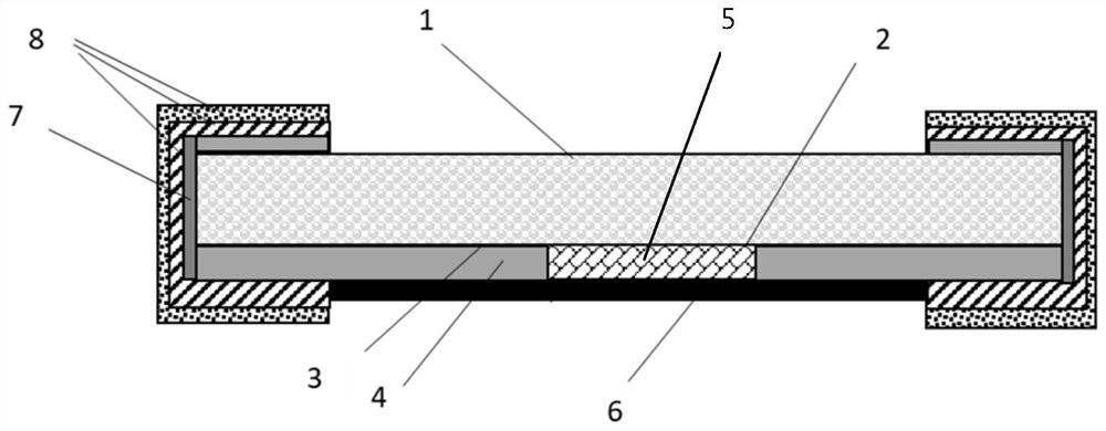
[0033] refer to figure 1 As shown, this embodiment provides a high-power alloy foil resistor, which is suitable for automobiles, industrial control and other precision electronic products or equipment.

[0034] The high-power alloy foil resistor includes: a substrate 1, a metal layer 2, an adhesive layer 3, a resistance element 4, an intermediate material 5, a protective layer 6, a side metal bottom layer 7 and an electrode terminal 8. The substrate 1 can be Soft insulating and heat-conducting materials such as alumina or aluminum nitride ceramics or polyimide after pre-cutting, the metal layer 2 can be a material that can be used for film growth processes such as deposition and sputtering, such as copper alloy, nickel-chromium alloy , one of titanium-tungsten alloys, the adhesive 3 can be applied on the surface of the substrate 1 by pressing, coating, etc. and combined with the resistance element, and the resistance el...

Embodiment 2

[0036] This embodiment is an embodiment of the manufacturing method for manufacturing the resistor in the first embodiment.

[0037] The manufacturing method of this resistor comprises the following steps:

[0038] Paste the glue 3 on the surface of soft insulating and heat-conducting materials 1 such as aluminum oxide or aluminum nitride ceramics or polyimide with cutting grooves, such as figure 2 As shown; in this step, the substrate is cut by laser to form a cutting groove on the substrate, the cutting depth is 30% to 60% of the thickness of the substrate, the laser power is 200 to 400W, the cutting speed is 500 to 1500mm / s, and the laser frequency is 40% to 90%. The width of the cutting blade used is 0.05-0.3 mm, the rotation speed of the cutting blade is 500-1800 rpm, and the material of the blade can be diamond or other hard alloy materials. Then stick the adhesive layer on the substrate with the cutting groove.

[0039] The resistance alloy piece and the intermediat...


PUM

PropertyMeasurementUnit
thicknessaaaaaaaaaa

Abstract

The invention discloses a high-power alloy foil resistor which comprises a substrate, a resistor element attached to the substrate and electrodes connected to the two ends of the resistor element. The resistor element comprises an intermediate material piece and two resistor alloy pieces, the middle material piece is clamped between the two resistance alloy pieces and is connected with the two resistance alloy pieces at the same time, the two resistance alloy pieces are connected with the electrodes at the two ends respectively, and the intermediate material piece is made of a low-resistivity high-thermal-conductivity metal material. As the middle area of the resistance element is replaced by the low-resistivity high-thermal-conductivity material, a heat accumulation area is divided into two parts. The heat accumulation points of the resistor element can be segmented, and a heat transmission path is shortened, so that the heat dissipation capability of the whole resistor is improved, and the service power of a product is improved. Meanwhile, the middle part of the resistor element is replaced by the low-resistivity metal, so that the designed length of the resistor element is reduced, and the resistor with a lower resistance value can be designed and produced.

Description

technical field [0001] The invention belongs to the field of designing circuit elements, especially alloy foil resistors. Background technique [0002] The power of the resistor is mainly determined by the heat dissipation capacity of the resistor, and the heat dissipation of the resistor mainly depends on the electrodes to transfer the heat in the resistive element to the mounted carrier, so as to achieve the purpose of reducing the heat in the resistive element. Under normal circumstances, the middle area of ​​the resistance element is relatively far away from the electrode, and the heat transmission path is long, which causes the heat in the middle area of ​​the resistance element to escape in time and form a heat accumulation point. If the heat is too high, the protective layer is damaged or the resistance value exceeds the accuracy requirement. , the product may fail. In addition, the production process of resistors needs to adjust the resistance value of the product b...

Claims


Application Information

Patent Timeline
Patent Type & Authority Applications(China)
IPC IPC(8): H01C1/084H01C7/00H01C17/00H01C17/12H01C17/075
CPCH01C1/084H01C7/001H01C17/00H01C17/12H01C17/075
Inventor 罗亚涛杨漫雪
Owner NANJING SART SCI & TECH DEV
Why Eureka
Try Eureka