Treatment method of oily sludge and sand

A treatment method, oil sludge sand technology, applied in sludge treatment, immiscible solvent sludge treatment, water/sludge/sewage treatment, etc., can solve the problem of large mechanical equipment wear, long process, and poor separation effect of oily sludge etc. to achieve the effect of reducing mechanical wear and ensuring the separation effect

Active Publication Date: 2021-07-16
CHINA PETROLEUM & CHEM CORP +1
View PDF21 Cites 4 Cited by
  • Summary
  • Abstract
  • Description
  • Claims
  • Application Information

AI Technical Summary

Problems solved by technology

[0010] In order to solve the problems of long flow process, large wear and tear on mechanical equipment, and poor separation effect of oily sludge in the prior art, the present invention provides a treatment method for oily sludge, which utilizes a purpose-designed feeder, washing machine, etc. The sander homogenizes and desands the oily sludge, and then uses the impeller agitator to flocculate and separate to obtain high-oily sludge and low-oily sludge with ideal separation effects; the treatment process has mild operating conditions, saves costs, reduces safety risks, There is no secondary environmental protection problem, and the processing efficiency is greatly improved

Method used


Image

  • Treatment method of oily sludge and sand
  • Treatment method of oily sludge and sand
  • Treatment method of oily sludge and sand

Examples


Embodiment 1

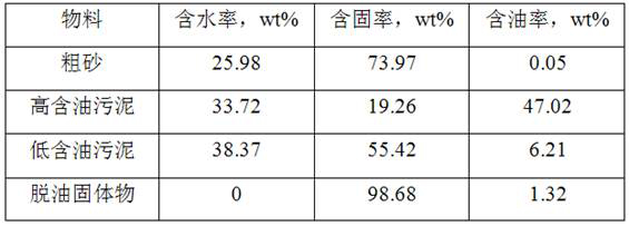
[0052] The raw materials used in this example are taken from the oil sludge sand in the production fluid produced by a joint station. The properties of the raw materials were analyzed, and the analysis results are shown in Table 1.

[0053] Table 1.

[0054]

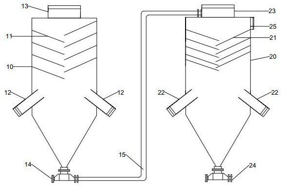
[0055] The above-mentioned oil sludge sand is processed sequentially through the feeder, sand washer and impeller agitator. The structure diagram of the feeder and sand washer is shown in figure 1 Shown:

[0056] The upper part of the feeder cylinder 10 is a cylindrical tank body and the lower part is a conical tank body. The feeder inlet 13 is set at the top center of the cylindrical tank body, and 8 staggered arrangements are arranged on both sides of the inner wall above the tank body. The feeder distribution plate 11, the feeder distribution plate 11 is arranged in the range from the top of the cylindrical tank body to the height of 1 / 2 cylindrical tank body from the top; the feeder distribution plate 11 is down...

Embodiment 2

[0064] In this embodiment, the scum produced by a refinery sewage treatment plant is used as the raw material of the oil sludge sand. The properties of the raw materials were analyzed, and the analysis results are shown in Table 3.

[0065] table 3.

[0066]

[0067] The above-mentioned oil sludge sand is processed sequentially through the feeder, sand washer and impeller agitator. The structure diagram of the feeder and sand washer is shown in figure 1 Shown:

[0068] The structure of the feeder and the sand washer is different from that in Example 1 in that the height of the cylindrical tank body of the feeder and the sand washer is different, and the distribution plate 11 of the feeder is 7 pieces, so as to form a 60° direction with the horizontal direction. The height of the gap between two adjacent feeder distribution plates 11 on the same side is 200mm; the distribution plate 21 of the sand washer is inclined downward at 15° from the horizontal direction, and the tw...

Embodiment 3

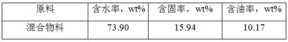
[0074] The raw materials used in this example are the raw materials used in Example 1 and Example 2 through equal mass mixing as oil sludge sand raw materials. The properties of the raw materials were analyzed, and the analysis results are shown in Table 5.

[0075] table 5.

[0076]

[0077] The above-mentioned oil sludge sand is processed sequentially through the feeder, sand washer and impeller agitator. The structure diagram of the feeder and sand washer is shown in figure 1 Shown:

[0078] The structure of the feeder and the sand washer is different from that in Example 1 in that the height of the cylindrical tank body of the feeder and the sand washer is different, and the distribution plate 11 of the feeder is 9 pieces, so as to form a 45° direction with the horizontal direction. The height of the gap between two adjacent feeder distribution plates 11 on the same side is 260mm; the distribution plate 21 of the sand washer is inclined downward at 15° from the horizont...


PUM

PropertyMeasurementUnit
dehydration rateaaaaaaaaaa

Abstract

The invention relates to a treatment method of an oily sludge and sand, which comprises the following steps of: adding oily sludge and sand into a specially designed feeder, forcibly mixing the oily sludge and sand with water after passing through a distribution plate to obtain homogenization treatment, conveying the treated material to a specially designed sand washer, separating out large-particle-size coarse sand particles under the impact of a multi-stage distribution plate and inlet water, conveying to an impeller agitator, under the action of microbubbles generated by an impeller, and settling the materials in a grading manner, wherein the upper scum layer is high-oil-content sludge, and the lower settling layer is low-oil-content sludge. According to the feeder and the sand washer, oil sludge and sand are fully homogenized through the arrangement of multi-stage distribution plates and a water inlet mixing mode, and coarse sand separation is achieved. The oil content of the high-oil-content sludge separated by the method is greater than or equal to 40%, and the water content is less than or equal to 50%; the oil content in the low-oil-content sludge is less than or equal to 6%, and the water content is less than or equal to 40%.

Description

technical field [0001] The invention belongs to the field of petrochemical industry and relates to a treatment method for oil sludge. Background technique [0002] Oily sludge is a hazardous waste produced in the process of petroleum refining and product manufacturing. Its composition is very complex. It not only contains crude oil components, but also has different production processes and mixed solids with different particle sizes. At present, the processes involved in each patent mainly focus on stirring, centrifugation and high-temperature treatment. [0003] Patent CN105668966 discloses a short-process oil sludge treatment system. The core treatment method of the system is the ultrasonic-assisted hot water washing method, and the oily mud sand is ultrasonically treated while stirring. The disadvantages of this method are as follows: (1) Even if there is ultrasonic cavitation Auxiliary, the treatment effect of hot water washing method is still very limited; (2) Oil slud...

Claims


Application Information

Patent Timeline
Patent Type & Authority Applications(China)
IPC IPC(8): C02F11/00C10G1/00C10G1/04
CPCC02F11/00C02F11/002C10G1/00C10G1/04C10G2300/1003C02F2303/06
Inventor 孙浩程回军刘春阳李宝忠王宜迪
Owner CHINA PETROLEUM & CHEM CORP
Why Eureka
Try Eureka