
A microwave plasma processing device

A technology of microwave plasma and processing equipment, applied in metal material coating process, coating, gaseous chemical plating, etc., can solve problems such as heat loss, uneven edges that meet uniformity requirements, and waste of production resources. Achieve uniform edge and achieve temperature uniformity

Active Publication Date: 2022-07-22
SHANGHAI ZHENGSHI TECH CO LTD
View PDF0 Cites 0 Cited by
  • Summary
  • Abstract
  • Description
  • Claims
  • Application Information

AI Technical Summary

Problems solved by technology

[0003] The plasma is in the form of a cloud, also called a plasma cloud. In the vapor deposition process, the plasma cloud needs to maintain a high temperature state. Once the temperature drops, the ionization will drop significantly, and the components will change from the plasma state to the conventional gas molecular state. It is beneficial to the deposition and formation of diamond film, and this effect mostly occurs at the edge of the plasma cloud, which is the junction of the plasma cloud and the surrounding gas, where heat exchange is performed and material exchange is less, and the heat provided by microwaves is easily lost. However, it affects the stability of the plasma state. Once the phase transition occurs, the diamond film here is no longer uniform and dense.
[0004] In the prior art, the range of the plasma is often adjusted by adjusting physical quantities or dimensions such as the height of the resonator, microwave power, antenna height, etc., so as to obtain a diamond film that meets the area requirements on the expected work base surface. Such an adjustment method First, it is difficult to control. In the area of ​​the generated diamond film, the edges that meet the uniformity requirements are uneven, with many burrs, and need to be trimmed to meet the use. Trimming will cut off a part of the area that meets the thickness composite requirements, wasting production resources

Method used


Image

  • A microwave plasma processing device
  • A microwave plasma processing device
  • A microwave plasma processing device

Examples


Embodiment Construction

[0023] The technical solutions in the embodiments of the present invention will be clearly and completely described below with reference to the accompanying drawings in the embodiments of the present invention. Obviously, the described embodiments are only a part of the embodiments of the present invention, but not all of the embodiments. Based on the embodiments of the present invention, all other embodiments obtained by those of ordinary skill in the art without creative efforts shall fall within the protection scope of the present invention.

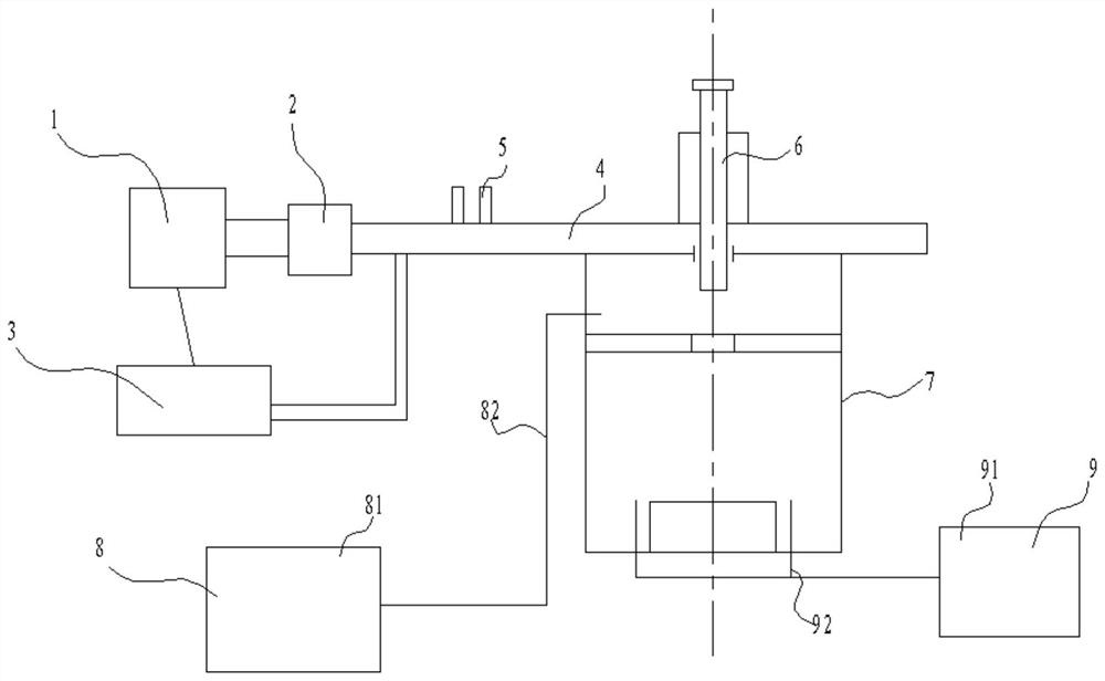
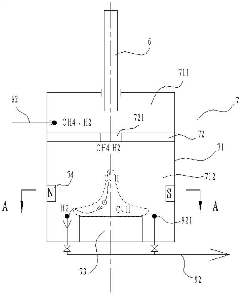
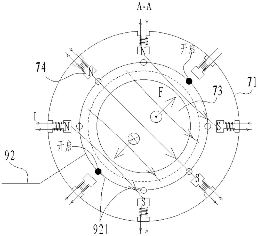
[0024] see Figure 1-5 , the present invention provides technical scheme:

[0025] A microwave plasma processing device, comprising a microwave source 1, a microwave circulator 2, a power regulator 3, a rectangular waveguide 4, a tuner 5, an antenna 6, a reaction box 7, a gas mixing system 8, a vacuum system 9, and a microwave source 1 The microwave circulator 2 is connected, the outlet end of the microwave circulator 2 is connected to...


PUM


Abstract

The invention discloses a microwave plasma processing device, comprising a microwave source, a microwave circulator, a power regulator, a rectangular waveguide, a tuner, an antenna, a reaction box, a gas mixing system, and a vacuum system. The microwave source is connected to the microwave circulator, and the microwave The exit end of the circulator is connected to the rectangular waveguide, and the power conditioner is connected to the exit end of the microwave circulator and the microwave source respectively. The power conditioner adjusts the excitation power of the microwave source according to the microwave output power. A tuner is set on the side wall of the rectangular waveguide, and the reaction box is installed in the rectangular waveguide. On the side of the end of the waveguide, the antenna is inserted into the rectangular waveguide and the top of the reaction box, the gas mixing system injects the working medium gas into the reaction box, and the vacuum system evacuates the reaction box and maintains a vacuum state; the plasma cloud in the reaction box is subjected to electromagnetic force. Inner loop.

Description

technical field [0001] The invention relates to the technical field of microwave plasma processing, in particular to a microwave plasma processing device. Background technique [0002] Microwave plasma processing is an emerging special processing method. Microwave plasma has high ionization degree, high electron temperature, electron density, and there is no electrode contamination. The plasma is properly controlled and will not cause pollution on the microwave path. Therefore, it is widely used in the industrial manufacture of diamond films. [0003] Plasma is cloud-like, also known as plasma cloud. In the vapor deposition process, the plasma cloud needs to be kept in a high temperature state. Once the temperature drops, the ionization decreases significantly, and the composition changes from the plasma state to the conventional gas molecule state. It is conducive to the deposition and formation of diamond film, and this effect mostly occurs at the edge of the plasma cloud...

Claims


Application Information

Patent Timeline
Patent Type & Authority Patents(China)
IPC IPC(8): C23C16/511C23C16/27
CPCC23C16/511C23C16/274
Inventor 龚闯朱长征吴剑波蒋剑宏
Owner SHANGHAI ZHENGSHI TECH CO LTD
Learn More