

Magnetotelluric inversion method based on full convolutional neural network
A convolutional neural network and convolutional neural technology, applied in the field of magnetotelluric inversion based on full convolutional neural network, can solve the problems of loss of position information, overfitting, slow network convergence, etc., and achieve high fitting accuracy , fast convergence speed, and the effect of reducing the loss of computing memory and time
- Summary
- Abstract
- Description
- Claims
- Application Information
AI Technical Summary
Problems solved by technology
Method used
Image

Examples
Embodiment 1
[0076] Example 1: Two-dimensional anomaly body inversion simulation model
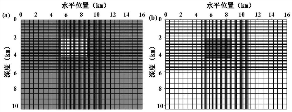
[0077] The high-resistance and low-resistance abnormal body models are established, and the rectangular grid is used for subdivision, and the input data of the simulation test model is obtained by forward calculation using the bilinear interpolation finite element method.
[0078] image 3 It is a schematic diagram of a test model sample and a grid distribution distribution provided by Embodiment 1 of the present invention, such as image 3 as shown, image 3 (a) in (a) means low resistance anomaly, (b) means high resistance anomaly; image 3 medium dark area ( image 3 In the peripheral area of (a), image 3 The middle rectangular area of (b) in (b) indicates high resistance, the range of resistivity is between 1000-1500Ω·m, and the light-colored area ( image 3 The middle rectangular area of (a), image 3 The peripheral area of (b)) indicates low resistance, and the resistivity ranges fro...
Embodiment 2
[0086] Example 2: Inversion of measured data
[0087] In this embodiment, a certain measuring line in the magnetotelluric field detection application test is selected for the inversion test. The measuring line is 12 km long, and the measurement point distance is 500 m. Some measuring points with large interference are removed, and a total of 20 measuring points are removed. The MT measurement in this work area adopts the self-developed equipment iEM-I electromagnetic method detection system, the receiver is DRU-1C type, and the magnetic sensor is IMC-03 type. The working frequency range of the system is 0.0001-10kHz, and the acquisition time is designed according to the minimum frequency required. The acquisition time of each measuring point in the working area is longer than 8 hours. The observation data of the 320-0.088Hz frequency band is intercepted, and the frequencies are distributed at equal logarithmic intervals, with a total of 48 frequency points.
[0088] Figure ...
PUM
| Property | Measurement | Unit |
|---|---|---|
| Resistivity value | aaaaa | aaaaa |
Abstract
Description
Claims
Application Information