
Photocatalytic in-situ Raman spectrum measurement system

A spectroscopic measurement and in-situ Raman technology, which is applied in the direction of measuring devices, Raman scattering, and material analysis through optical means, to achieve the effects of improving sensitivity, reducing interference, and simple and compact structure

Active Publication Date: 2021-08-06
NANJING UNIV OF SCI & TECH
View PDF2 Cites 3 Cited by
  • Summary
  • Abstract
  • Description
  • Claims
  • Application Information

AI Technical Summary

Problems solved by technology

[0005] The purpose of the present invention is to address the above problems, design a photocatalytic in-situ Raman spectroscopy measurement system that realizes the coupling of Raman excitation light and photocatalytic beam, and solve the problem of reducing Rayleigh scattered light and photocatalytic beam in the broadband photocatalytic excitation system interference problem

Method used


Image

  • Photocatalytic in-situ Raman spectrum measurement system
  • Photocatalytic in-situ Raman spectrum measurement system
  • Photocatalytic in-situ Raman spectrum measurement system

Examples


Embodiment 1

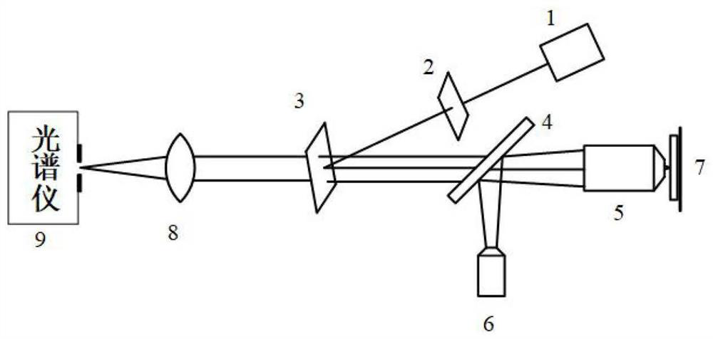
[0041] Such as figure 1 A backscattering photocatalytic in-situ Raman spectroscopy measurement system shown mainly consists of a Raman laser 1, a narrow-band filter 2, a band-stop filter 3, a beam splitter 4, an objective lens 5, a photocatalytic light source 6, Composed of photocatalytic reactor 7, focusing lens 8 and spectrometer 9;

[0042] Raman laser 1, narrow-band filter 2, band-rejection filter 3, spectroscope 4, objective lens 5, and photocatalytic reactor 7 are sequentially arranged on the incident optical path of Raman excitation light, and band-rejection filter 3 will pass through The laser light transmitted by the narrow-band filter 2 is reflected to the beam splitter 4, and the beam splitter 4 is arranged on the transmission optical path of the Raman excitation light for combining the Raman excitation light and the light beam of the photocatalytic light source 6 and passing the beam along the objective lens The optical axis of 5 is introduced into objective lens ...

Embodiment 2

[0056] Such as Figure 6 A lateral photocatalytic in situ Raman spectroscopy measurement system shown or as Figure 7 A transmissive photocatalytic in-situ Raman spectroscopy measurement system is shown, including a Raman laser 1, a narrow-band filter 2, a beam splitter 4, an objective lens 5 and a photocatalytic reaction device 7, and the sequentially arranged first focusing lens 8, band-stop filter 3, second focusing lens 10 and spectrometer 9 for Raman signal collection, also includes photocatalytic light source 6; photocatalytic light source 6 The light beam is reflected by the beam splitter 4 and the Raman excitation light and beam and is imported into the objective lens 5 along the optical axis of the objective lens 5, and the objective lens 5 is used to focus the Raman excitation light and the light beam of the photocatalytic light source 6 on the photocatalytic reactor 7 In the sample to be measured; the first focusing lens 8 is arranged behind the photocatalytic reac...


PUM

PropertyMeasurementUnit
angle of incidenceaaaaaaaaaa

Abstract

The invention discloses a back scattering type photocatalytic in-situ Raman spectrum measurement system and a transmission type or lateral type photocatalytic in-situ Raman spectrum measurement system. The back scattering type photocatalytic in-situ Raman spectrum measurement system comprises a Raman laser, a narrow-band filter, a band-stop filter, a spectroscope, an objective lens, a photocatalytic light source, a photocatalytic reactor, a focusing lens and a spectrograph. The spectroscope is arranged on a transmission light path of the Raman exciting light and is used for combining the Raman exciting light and the photocatalytic light beam and guiding the combined light beam into the objective lens along the optical axis of the objective lens, and the objective lens focuses the Raman exciting light and the photocatalytic light beam on a sample; the back scattering Raman signal light is collected by the objective lens, is transmitted by the spectroscope and the band-stop filter, and is converged at a light inlet of the spectrograph through the focusing lens; and a transmitted or laterally scattered Raman signal is collected by the first focusing lens, passes through the band-stop filter and is converged at a light inlet of the spectrometer by the second focusing lens. According to the invention, the coupling of the Raman exciting light and the photocatalytic light beam is ensured, and the device is suitable for the in-situ Raman measurement of various photocatalytic reaction systems.

Description

technical field [0001] The invention relates to the technical field of in-situ Raman spectrum measurement, in particular to a photocatalytic in-situ Raman spectrum measurement system. Background technique [0002] The use of cheap, clean, and sustainable solar energy to drive photocatalytic reactions, including solar photolysis of water to produce hydrogen, photocatalytic reduction of carbon dioxide, photocatalytic degradation of pollutants, and photocatalytic synthesis, has important application value in the fields of energy and the environment. , which has become a research hotspot in recent years. The efficiency of the photocatalytic system is affected by factors such as catalyst properties, light source, and reactor conditions. Therefore, research on the photocatalytic reaction mechanism is the only way to clarify the reaction process and optimize the catalytic system. [0003] Raman spectroscopy can not only identify the chemical structure and crystal form of substance...

Claims


Application Information

Patent Timeline
Patent Type & Authority Applications(China)
IPC IPC(8): G01N21/65G01N21/01
CPCG01N21/65G01N21/01Y02W10/37
Inventor 张莹陈鑫悦刘东冯浩李强
Owner NANJING UNIV OF SCI & TECH
Learn More