High-speed aviation rotor blade tip grinding machine

A rotor and aviation technology, applied in grinding machines, grinding bed, grinding machine parts, etc., can solve problems affecting the working efficiency and reliability of the engine, poor consistency of the rotor tip, and difficulty in controlling the clearance between the tip and the casing and other problems to achieve the effect of improving processing quality, improving processing efficiency and reducing complexity

Pending Publication Date: 2021-08-13
台州中驰智谷科技有限公司
View PDF0 Cites 2 Cited by
  • Summary
  • Abstract
  • Description
  • Claims
  • Application Information

AI Technical Summary

Problems solved by technology

The disadvantage of this process is that the spindle speed of the lathe can only rotate at a low speed when the blade tip is ground, and the blade tip is ground at a low speed. In order to cope with the grinding force during the blade tip grinding, a rubber belt is used to carry out Bundling, the final result is that the consistency of the rotor blade tip is poor, and it is difficult to control the gap between the blade tip and the casing, which seriously affects the efficiency and reliability of the engine.

Method used


Image

  • High-speed aviation rotor blade tip grinding machine
  • High-speed aviation rotor blade tip grinding machine
  • High-speed aviation rotor blade tip grinding machine

Examples


Embodiment Construction

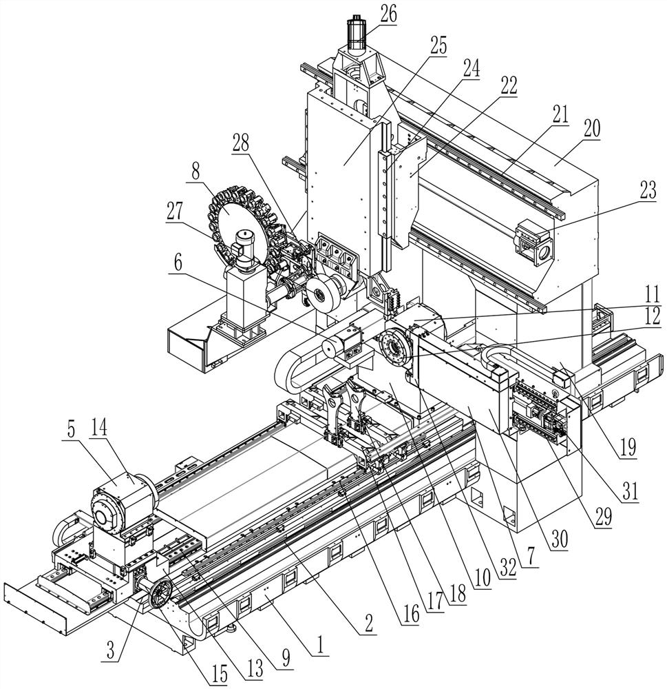
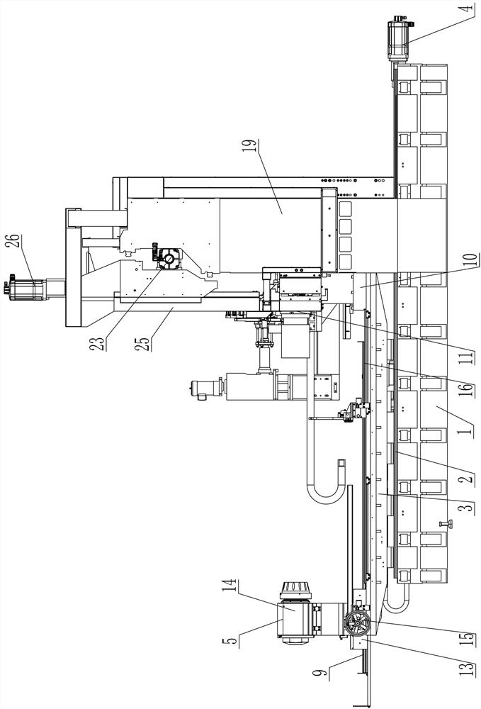
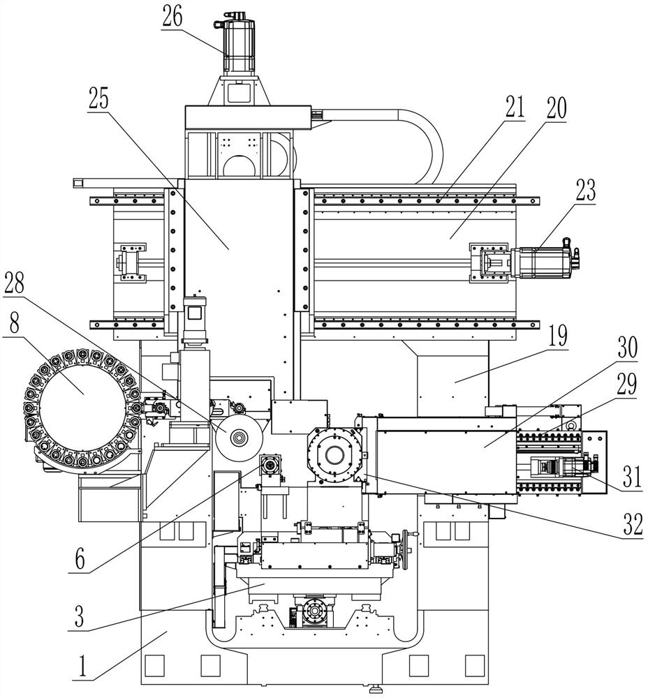
[0029] The following will be combined with Figure 1-4 The present invention is described in further detail.

[0030] A high-speed aviation rotor blade tip grinder, comprising a base 1 arranged horizontally, on which an X-axis guide rail 2 arranged horizontally and horizontally is arranged, on which an X-axis moving frame 3 slidingly connected with the X-axis guide rail 2 is arranged, and the base 1 is provided with a first drive mechanism 4 that drives the X-axis moving frame 3 to move on the X-axis guide rail 2. The base 1 can be set to a sufficient length as required, so that the effective moving distance of the X-axis moving frame 3 is large enough, and can be moved out of the processing area of ​​the grinding spindle to facilitate the hoisting of workpieces.

[0031] The X-axis mobile frame 3 is equipped with a spindle clamping mechanism 5 for placing the product to be processed, and the X-axis mobile frame 3 is equipped with a grinding wheel dresser 6, which can correct...


PUM


Abstract

The invention belongs to the technical field of machining, and particularly relates to a high-speed aviation rotor blade tip grinding machine. The machine comprises a horizontally-arranged base, wherein an X-axis guide rail is arranged on the base, an X-axis moving frame is connected to the X-axis guide rail in a sliding manner, and a first driving mechanism for driving the X-axis moving frame to move is arranged on the base. A main shaft clamping mechanism and a grinding wheel dresser are arranged on the X-axis moving frame. An optical measuring mechanism and a multi-station grinding wheel library are arranged on the two sides of the X-axis moving frame. A portal frame is erected above the X-axis guide rail and comprises stand columns and a cross beam, a Y-axis guide rail horizontally arranged in the longitudinal direction is arranged on the cross beam of the portal frame, a Y-axis moving frame is connected to the Y-axis guide rail in a sliding manner, and a second driving mechanism for driving the Y-axis moving frame to move is arranged on the cross beam. A Z-axis guide rail arranged in the vertical direction is arranged on the Y-axis moving frame, a lifting frame is connected to the Z-axis guide rail in a sliding manner, a third driving mechanism for driving the lifting frame to move is arranged on the Y-axis moving frame, and a grinding wheel mechanism is arranged at the bottom of the lifting frame. The device is simple in structure and high in reliability.

Description

technical field [0001] The invention belongs to the technical field of mechanical processing, and in particular relates to a high-speed aviation rotor tip grinder. Background technique [0002] Most domestic aero-engine OEMs use slow-speed blade tip grinding equipment. This type of equipment is not special equipment purchased ready-made in China. Instead, the equipment department of the aero-engine OEM adopts ordinary lathes, and the bed of ordinary lathes is used. , main shaft, and tailstock, and the grinding head is added on the slide plate of the tool post of the machine tool to realize the purpose of rotor blade tip grinding. The disadvantage of this process is that the spindle speed of the lathe can only rotate at a low speed when the blade tip is ground, and the blade tip is ground at a low speed. In order to cope with the grinding force during the blade tip grinding, a rubber belt is used to carry out Bundling, the final result is that the consistency of the rotor bl...

Claims


Application Information

Patent Timeline
Patent Type & Authority Applications(China)
IPC IPC(8): B24B19/14B24B9/04B24B41/06B24B41/02B24B41/04B24B47/12B24B53/06B24B53/12B24B41/00
CPCB24B9/04B24B19/14B24B41/00B24B41/02B24B41/04B24B41/06B24B47/12B24B53/06B24B53/12
Inventor 季海风
Owner 台州中驰智谷科技有限公司
Why Eureka
Try Eureka