Silicon carbide crystal growth method and equipment capable of adjusting component balance

A technology of crystal growth and silicon carbide, applied in crystal growth, single crystal growth, single crystal growth and other directions, can solve the problems of waste of raw materials, affecting the yield and product quality of downstream processes, affecting the quality of silicon carbide crystals, etc., to save costs , to prevent corrosion, to avoid the effect of screw dislocation

Active Publication Date: 2021-08-13
SUZHOU UKING PHOTOELECTRIC TECH CO LTD
View PDF6 Cites 8 Cited by
  • Summary
  • Abstract
  • Description
  • Claims
  • Application Information

AI Technical Summary

Problems solved by technology

[0003] But at high temperature, silicon (Si) element and silicon-rich atomic groups are easier to escape from the raw material and transported into the growth chamber space, so the silicon element in the raw material is faster than the carbon (C) element during the crystal growth process. The carbonization of the raw material (that is, the C content in the raw material is higher than the Si content), after carbonization, the raw material will produce carbon-rich atomic groups, which will deposit on the crystal to form inclusion defects, and the inclusion defects will further grow into screw dislocations, layer Larger-scale defects such as faults and micropipes seriously affect the crystal quality of silicon carbide, which in turn affects the yield and product quality of downstream processes such as epitaxial process and device process; at the same time, crystal growth must be stopped when the raw material carbonization is serious, resulting in A large amount of waste, the ratio of the weight of crystals obtained in the industry to the weight of raw materials input is less than one-third, and the waste of raw materials is serious

Method used


Image

  • Silicon carbide crystal growth method and equipment capable of adjusting component balance
  • Silicon carbide crystal growth method and equipment capable of adjusting component balance

Examples


Embodiment 1

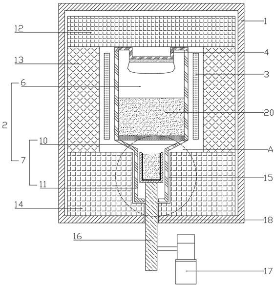
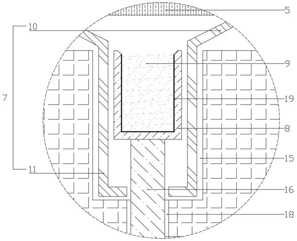
[0033] Such as figure 1 As shown, a silicon carbide crystal growth device for adjusting component balance includes a cavity 1, a graphite crucible 2 fixed in the cavity 1 and a heater 3, and a growth tank 4 arranged on the top of the graphite crucible 2, the graphite A porous partition 5 is horizontally arranged in the crucible 2, and the porous partition 5 divides the graphite crucible 2 into a crystal growth chamber 6 and an auxiliary chamber 7. The crystal growth chamber 6 is filled with a silicon carbide raw material 20, combined with figure 2 The auxiliary chamber 7 is movably connected with an auxiliary crucible 8 through a lifting assembly, and the auxiliary crucible 8 is filled with a silicon-rich raw material 9; the heater 3 evenly heats the crystal growth chamber 6 .

[0034] The heater 3 is a graphite heater.

[0035] Described auxiliary chamber 7 comprises the area surrounded by conical plate 10 and the area enclosed by cylindrical plate 11 that links to each oth...

Embodiment 2

[0042] A silicon carbide crystal growth method for adjusting component balance, comprising the steps of:

[0043] S1. Preheating stage: Fill the silicon carbide raw material 20 into the crystal growth chamber 6 of the graphite crucible 2, and fill the silicon-rich raw material 9 into the auxiliary crucible 8 located at the bottom of the auxiliary chamber 7, the silicon-rich raw material 9 is silicon carbide and Silicon mixture, check the tightness of chamber 1, vacuumize to 3Pa in chamber 1, and further evacuate to 10Pa in chamber 1 -2 Pa, adjust the heater 3 to make the temperature in the cavity 1 reach 500°C, fill the cavity 1 with hydrogen and nitrogen, and maintain the pressure in the cavity 1 at 50Pa;

[0044] S2. The first stage of crystal growth stage: adjust the heater 3 to raise the temperature of the chamber 1 to 2000°C;

[0045] S3. The second stage of crystal growth stage: when the crystal in the growth tank 4 grows to the 1 / 3N stage, start the lifting motor 17, a...

Embodiment 3

[0047] A silicon carbide crystal growth method for adjusting component balance, comprising the steps of:

[0048] S1. Preheating stage: Fill the silicon carbide raw material 20 into the crystal growth chamber 6 of the graphite crucible 2, and fill the auxiliary crucible 8 located at the bottom of the auxiliary chamber 7 with a silicon-rich raw material 9, which is a compound of silicon (silicon dioxide), check the tightness of cavity 1, evacuate until the pressure in cavity 1 is 0.1Pa, and further evacuate until the pressure in cavity 1 is 10 -3 Pa, adjust the heater 3 to make the temperature in the cavity 1 reach 550°C, fill the cavity 1 with nitrogen and argon, and maintain the pressure in the cavity 1 as 100Pa;

[0049] S2. The first stage of crystal growth stage: adjust the heater 3 to raise the temperature of the cavity 1 to 2100°C;

[0050] S3. The second stage of crystal growth stage: when the crystal in the growth tank 4 grows to the 1 / 5N stage, start the lifting moto...


PUM


Abstract

The invention provides a silicon carbide crystal growth method and equipment capable of adjusting component balance, the equipment comprises a cavity, a graphite crucible, a heater and a growth tank, the graphite crucible and the heater are fixed in the cavity, a porous partition plate is horizontally arranged in the graphite crucible, the porous partition plate divides the graphite crucible into a crystal growth cavity and an auxiliary cavity, a silicon carbide raw material is contained in the crystal growth cavity, an auxiliary crucible is movably connected in the auxiliary cavity through a lifting assembly, and a silicon-rich raw material is contained in the auxiliary crucible; and the heater is used for uniformly heating the crystal growth cavity. The equipment comprises the graphite crucible and the auxiliary crucible adjusted by the lifting assembly, and along with continuous growth of crystals, the height of the auxiliary crucible is adjusted by the lifting assembly, so that silicon elements are supplemented into a silicon carbide raw material in the crystal growth process, and the balance of carbon components and silicon components in the silicon carbide raw material is adjusted; and the defects such as spiral dislocation, dislocation and microtubulation of silicon carbide crystals are avoided, and meanwhile the utilization rate of silicon carbide raw materials is increased.

Description

technical field [0001] The invention relates to a silicon carbide crystal growth method and equipment for adjusting component balance, and belongs to the technical field of silicon carbide crystal growth. Background technique [0002] The industrial growth of silicon carbide crystals mainly adopts the physical vapor transport (PVT) method, that is, the gas generated by the sublimation and decomposition of silicon carbide raw materials is transported to the seed crystal for recrystallization by heating above 2100 ° C, and a larger area of ​​silicon carbide (SiC ) single crystal. [0003] But at high temperature, silicon (Si) element and silicon-rich atomic groups are easier to escape from the raw material and transported into the growth chamber space, so the silicon element in the raw material is faster than the carbon (C) element during the crystal growth process. The carbonization of the raw material (that is, the C content in the raw material is higher than the Si content...

Claims


Application Information

Patent Timeline
Patent Type & Authority Applications(China)
IPC IPC(8): C30B29/36C30B23/00
CPCC30B23/00C30B29/36
Inventor 陈建明姜树炎周元辉刘春艳杨洪雨
Owner SUZHOU UKING PHOTOELECTRIC TECH CO LTD
Why Eureka
Try Eureka