Silicon carbide crystal growth method and equipment for supplementing gaseous carbon source and silicon source

A technology of crystal growth and gaseous carbon source, applied in the directions of crystal growth, single crystal growth, single crystal growth, etc., can solve the problems of waste of raw materials, affecting the yield and product quality of downstream processes, affecting the quality of silicon carbide crystals, etc. Purity, avoid screw dislocation, improve the effect of utilization

Pending Publication Date: 2021-10-15
SUZHOU UKING PHOTOELECTRIC TECH CO LTD
View PDF0 Cites 7 Cited by
  • Summary
  • Abstract
  • Description
  • Claims
  • Application Information

AI Technical Summary

Problems solved by technology

[0003] But at high temperature, silicon (Si) element and silicon-rich atomic groups are easier to escape from the raw material and transported into the growth chamber space, so the silicon element in the raw material is faster than the carbon (C) element during the crystal growth process. The carbonization of the raw material (that is, the C content in the raw material is higher than the Si content), after carbonization, the raw material will produce carbon-rich atomic groups, which will deposit on the crystal to form inclusion defects, and the inclusion defects will further grow into screw dislocations, layer Larger-scale defects such as faults and micropipes seriously affect the crystal quality of silicon carbide, which in turn affects the yield and product quality of downstream processes such as epitaxial process and device process; at the same time, crystal growth must be stopped when the raw material carbonization is serious, resulting in A large amount of waste, the ratio of the weight of crystals obtained in the industry to the weight of raw materials input is less than one-third, and the waste of raw materials is serious

Method used


Image

  • Silicon carbide crystal growth method and equipment for supplementing gaseous carbon source and silicon source
  • Silicon carbide crystal growth method and equipment for supplementing gaseous carbon source and silicon source
  • Silicon carbide crystal growth method and equipment for supplementing gaseous carbon source and silicon source

Examples


Embodiment 1

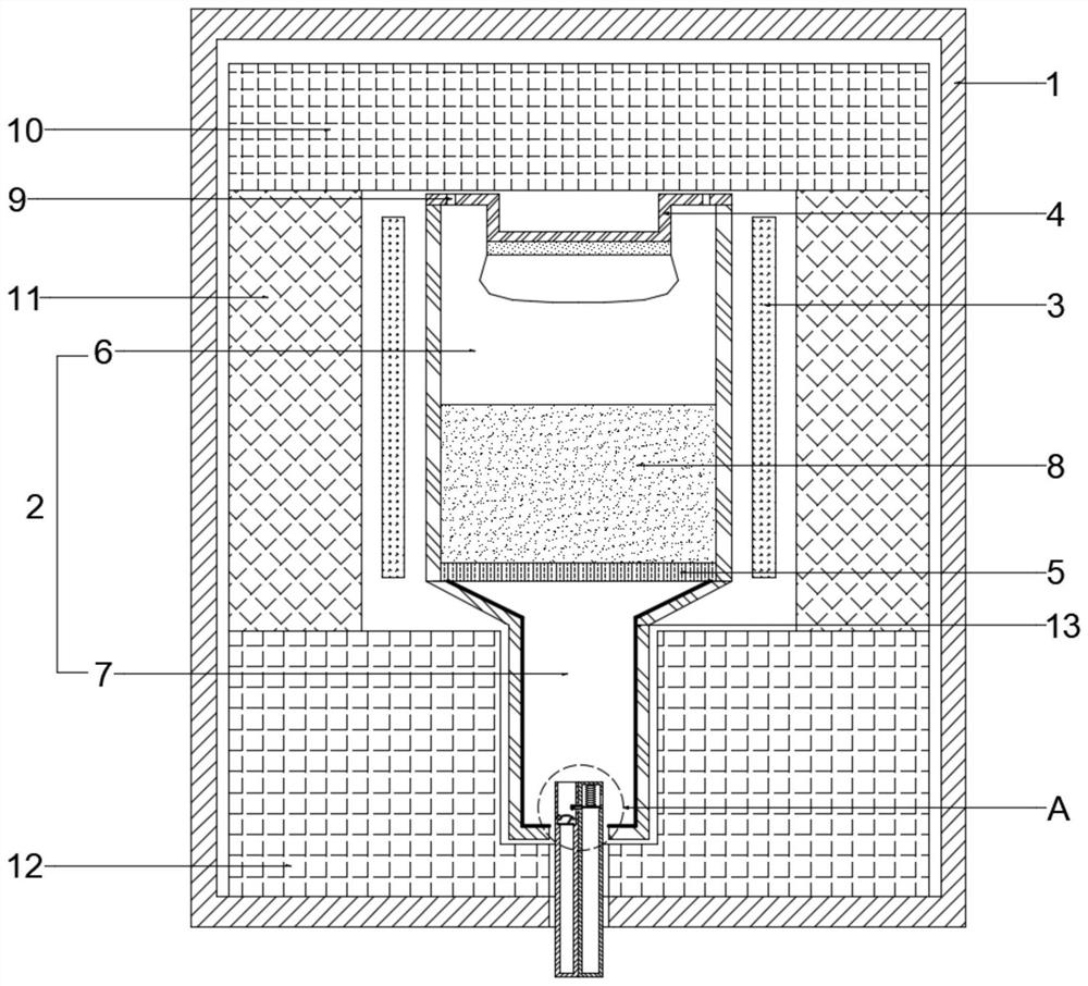
[0033] Such as figure 1 As shown, a silicon carbide crystal growth equipment supplementing gaseous carbon source and silicon source includes a furnace body 1, a graphite crucible 2 fixed in the furnace body 1, a heater 3, and a growth tank 4 arranged on the top of the graphite crucible 2, The graphite crucible 2 is horizontally provided with a porous partition 5, and the porous partition 5 divides the graphite crucible 2 into a crystal growth chamber 6 and a gas diffusion chamber 7. The height of the crystal growth chamber 6 is defined as M, and the crystal growth chamber 6 is used for Filled with silicon carbide raw material 8, the upper edge of the gas diffusion chamber 7 is set in the area from 1 / 3M above the porous partition 5 to the horizontal centerline of the porous partition 5. In this embodiment, the gas diffusion chamber 7 is integrally connected to Below the crystal growth chamber 6 , the bottom of the gas diffusion chamber 7 is fixedly connected with an intake asse...

Embodiment 2

[0041] Such as Figure 4 As shown, different from Embodiment 1, the upper edge position of the gas diffusion chamber 7 in this embodiment and Embodiment 1 is set differently. In Embodiment 1, the gas diffusion chamber 7 is integrally connected under the crystal growth chamber 6, that is, the gas diffusion chamber The upper edge of 7 is set at the horizontal centerline of the porous partition 5, and in this embodiment, the upper edge of the gas diffusion chamber 7 is set at a height of 1 / 8M above the porous partition 5 and surrounds the porous partition 5 and the bottom edge of the crystal growth chamber 6, the upper edge of the gas diffusion chamber 7 is set within the height of 1 / 3M above the porous partition plate 5, and the side walls of the surrounded crystal growth chamber 6 are provided with several The through holes with the same pore diameter of the separator 5 can make the gaseous carbon source and the gaseous silicon source supplement the silicon carbide raw material...

Embodiment 3

[0043] A method for growing silicon carbide crystals supplementing a gaseous carbon source and a silicon source, using the structure in Example 1, comprising the steps of:

[0044] S1. Preheating stage: fill the silicon carbide raw material 8 in the crystal growth chamber 6 of the graphite crucible 2, check the tightness of the furnace body 1, start the vacuum device (not shown) arranged at the bottom of the furnace body 1, Vacuumize until the pressure in the furnace body 1 is about 5 Pa, and further evacuate until the pressure in the furnace body 1 is at 10 Pa. -2 About Pa, adjust the heater 3 to make the temperature in the furnace body 1 reach about 500°C, and fill the furnace body 1 with a mixed gas of nitrogen and helium with a volume ratio of 1:5 to 1:20 through the air intake assembly to maintain the temperature of the furnace body. The pressure in the body 1 is about 10000Pa;

[0045] S2. The first stage of heating up: adjust the heater 3 to raise the temperature of th...


PUM


Abstract

The invention provides a silicon carbide crystal growth method and equipment for supplementing a gaseous carbon source and a silicon source, the equipment comprises a furnace body, a graphite crucible heater and a growth tank, a porous partition plate is arranged in the graphite crucible and divides the graphite crucible into a crystal growth cavity and a gas diffusion cavity, the height of the crystal growth cavity is defined as M, the upper edge of the gas diffusion cavity is arranged in an area from the position 1/3M above the porous partition plate to the horizontal center line of the porous partition plate, and the bottom of the gas diffusion cavity is fixedly connected with a gas inlet assembly; and the heater is used for uniformly heating the crystal growth cavity. The equipment comprises the crystal growth cavity and the gas diffusion cavity, and components are adjusted by supplementing the gaseous carbon source and the silicon source, so that the balance of the carbon component and the silicon component in the space near a silicon carbide crystal is kept in the crystal growth process, and the defects of spiral dislocation, stacking fault, microtubule and the like of the silicon carbide crystal are avoided, and the utilization rate of silicon carbide raw materials is improved.

Description

technical field [0001] The invention relates to a silicon carbide crystal growth method and equipment for supplementing gaseous carbon sources and silicon sources, and belongs to the technical field of silicon carbide crystal growth. Background technique [0002] The industrial growth of silicon carbide crystals mainly adopts the physical vapor transport (PVT) method, that is, the gas generated by the sublimation and decomposition of silicon carbide raw materials is transported to the seed crystal for recrystallization by heating above 2100 ° C, and silicon carbide (SiC) with a large area is obtained. ) single crystal. [0003] But at high temperature, silicon (Si) element and silicon-rich atomic groups are easier to escape from the raw material and transported into the growth chamber space, so the silicon element in the raw material is faster than the carbon (C) element during the crystal growth process. The carbonization of the raw material (that is, the C content in the ...

Claims


Application Information

Patent Timeline
Patent Type & Authority Applications(China)
IPC IPC(8): C30B29/36C30B23/00
CPCC30B29/36C30B23/00
Inventor 陈建明周元辉姜树炎刘春艳滕松
Owner SUZHOU UKING PHOTOELECTRIC TECH CO LTD
Why Eureka
Try Eureka