Pressure sensor and preparation method thereof

A technology of pressure sensor and piezoresistor, which is applied in the field of sensors, can solve the problems of large vibration and shock load, poor linearity, poor plasticity and flexibility, etc.

Pending Publication Date: 2021-08-13
SHENZHEN MEISI XIANRUI ELECTRONICS CO LTD
View PDF0 Cites 2 Cited by
  • Summary
  • Abstract
  • Description
  • Claims
  • Application Information

AI Technical Summary

Problems solved by technology

[0004] The purpose of the present invention is to provide a pressure sensor and its preparation method, which can overcome the above-mentioned problems such as poor linearity, unstable structure, poor plasticity and flexibility, and unsuitability for working conditions with large vibration and impact loads.

Method used


Image

  • Pressure sensor and preparation method thereof
  • Pressure sensor and preparation method thereof
  • Pressure sensor and preparation method thereof

Examples


Embodiment 1

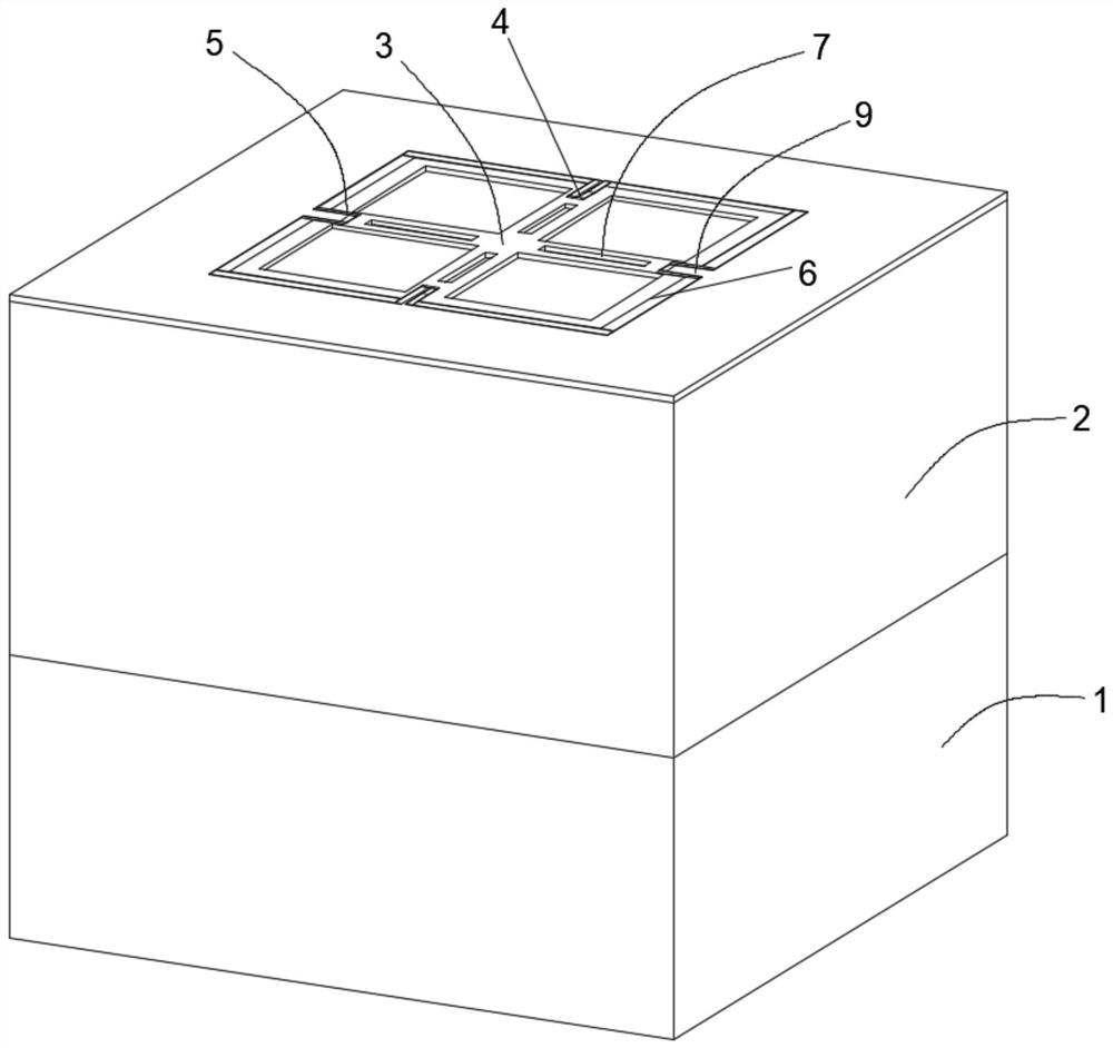
[0048] Such as figure 1 As shown, a pressure sensor, a MEMS piezoresistive pressure sensor designed and developed using MEMS technology, includes a glass base 1 and a silicon strain diaphragm 2 on the glass base 1, and the silicon strain diaphragm Sheet 2 is a silicon film with front beam film and back cavity structure formed by SOI wafer / silicon wafer through front etching and back cavity etching process;

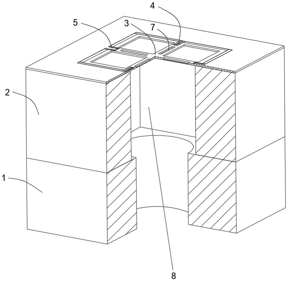
[0049] Such as figure 1 or figure 2 As shown, one side of the glass base 1 is provided with a concave cavity, and the silicon strain diaphragm 2 includes an insulating dielectric layer on the front side and a silicon substrate covered by the insulating dielectric layer, wherein the silicon substrate is an N-type crystal plane SOI (Silicon-On-Insulator) silicon wafer or N-type silicon wafer, and the silicon strain diaphragm 2 and the glass base 1 with a concave cavity are anodically bonded, which can bond the non-bonding surface of the silicon wafer Thinning, because t...

Embodiment 2

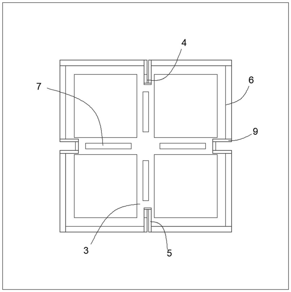
[0059] This embodiment discloses a method for preparing a pressure sensor. Multiple groups of piezoresistors 4 are fabricated at the midpoint of the sideline of a square diaphragm made by a back cavity etching process, and the number of piezoresistors 4 in each group is arbitrary. In this embodiment, there are four pieces; the front surface of the silicon strain diaphragm 2 is shallowly etched with a cross-beam structure, and the piezoresistor 4 is located on the cross-beam structure and at the edge of the cross-beam structure, and the piezoresistor 4 is located in the stress concentration area . Specifically, the steps of the method include:

[0060] 1) Chip preparation, marking layer etching: For N-type crystal plane SOI (Silicon-On-Insulator) silicon wafer zero-layer alignment etching mark, thermal oxygen on the surface of the silicon wafer Silica, such as Figure 4A shown;

[0061] 2) Photolithographic varistor 4: photolithographic varistor 4 pattern in the SOI silico...


PUM


Abstract

The invention provides a pressure sensor and a preparation method thereof, the pressure sensor comprises a glass base and a silicon strain diaphragm located on the glass base, one surface of the glass base is provided with a recessed cavity, and the silicon strain diaphragm comprises an insulating medium layer located on the front surface and a silicon substrate covered by the insulating medium layer; and a beam membrane structure of a cross beam structure is arranged at the position, facing the cavity, of the front face of the silicon strain membrane, each end of the beam membrane structure is provided with a set of piezoresistors, a set of heavily-doped contact areas and a pair of metal leads, the piezoresistors are connected with the heavily-doped contact areas in series, and the two ends of the piezoresistors are led out of the heavily-doped contact areas through the metal leads, the metal leads and the heavily doped contact regions form ohmic contact on the front surface of the silicon strain diaphragm, and Wheatstone bridges are formed among the varistors; the beam membrane structure comprises a plurality of groove structures arranged on the cross beam and is used for adjusting the performance of the pressure sensor to adapt to different measuring ranges; and the sensor is higher in linearity, more stable in structure and suitable for different measuring ranges.

Description

technical field [0001] The invention relates to the technical field of sensors, in particular to a pressure sensor and a preparation method thereof. Background technique [0002] The MEMS piezoresistive pressure sensor is based on the piezoresistive effect of single crystal silicon to convert the external pressure change into a corresponding electrical signal, and realizes the measurement of the external pressure by forming a Wheatstone bridge with four equivalent resistances. MEMS piezoresistive pressure sensors are mainly used in related fields such as industrial control, automotive electronics, consumer electronics, medical electronics, and aerospace. The MEMS piezoresistive pressure sensor adopts MEMS technology for design and process development. It uses silicon diaphragms obtained from silicon wafers as force-sensing elements, and four pairs of equivalent resistance and low It is composed of a multi-functional layer integrated with various materials such as interconne...

Claims


Application Information

Patent Timeline
Patent Type & Authority Applications(China)
IPC IPC(8): G01L9/00G01L9/06
CPCG01L9/0047G01L9/0051G01L9/0054G01L9/06G01L2009/0067
Inventor 武斌许克宇
Owner SHENZHEN MEISI XIANRUI ELECTRONICS CO LTD
Why Eureka
Try Eureka