Impurity removal device for non-edible salt processing
A technology of edible salt and heating unit, which is applied in the field of impurity removal devices for non-edible salt processing, and can solve problems such as heavy snow road closures, reactant content, and device corrosion
- Summary
- Abstract
- Description
- Claims
- Application Information
AI Technical Summary
Problems solved by technology
Method used
Image
Examples
Embodiment 1
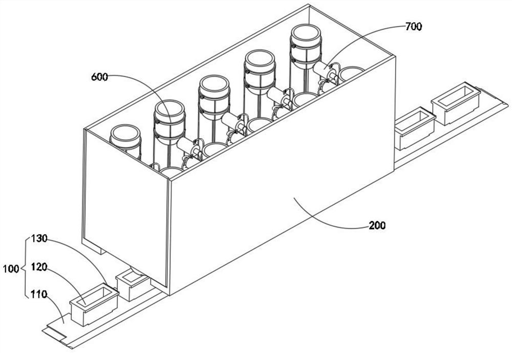
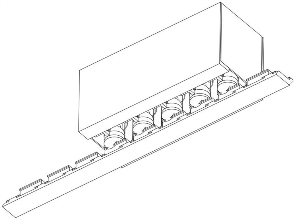
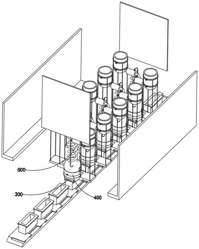
[0057] combine Figure 4 , 7 , 9, 11, 12 and 13, the impurity removal device for non-edible salt processing provided by the present invention includes a loading assembly 100, a protective casing 200, a sealing assembly 300, a heat energy conversion assembly 400, a snow melting salt reaction mechanism 500, and a supporting assembly 600 and the gas-liquid splitting mechanism 700, wherein the support assembly 600 is installed in the protective shell 200, and the gas-liquid splitting mechanism 700 is connected to the solution cylinder 630 in the support assembly 600, the loading assembly 100 is located at the bottom of the protective shell 200, and the loading assembly 100 The storage box 120 inside is plugged into the stopper 310 in the sealing assembly 300 , in addition, the sealing assembly 300 is connected to the snow melting salt reaction mechanism 500 , and the thermal energy conversion assembly 400 is installed outside the snow melting salt reaction mechanism 500 .
[0058...
Embodiment 2
[0061] combine Figure 4 As shown, according to the above-mentioned first embodiment, the storage box 120 is plugged into the chute at the top of the conveyor belt 110. At this time, after the storage box 120 passes through the chute at the bottom of the stopper 310, the conveyor belt 110 moves along the vertical direction. Ascent, and then can make the concentrated and crystallized product can be quickly discharged, the loading assembly 100 includes a conveyor belt 110 , a storage box 120 plugged into the inside of the rectangular slot, and an adhesive tape 130 installed on the top side of the storage box 120 .
Embodiment 3
[0063] combine Figure 9 As shown, in the above embodiment, the packaging film 320 is movably installed on one side of the chute at the bottom of the limiting member 310 through the insertion rod, and the side of the packaging film 320 with partial adhesion is surrounded along the outside of the pressure member 330, After the storage box 120 is plugged into the chute at the bottom of the stopper 310, the port stretched out from the packaging film 320 will be pasted on the adhesive tape 130, and finally be packaged along the top surface of the storage box 120. In the initial state, the telescopic member 523 pushes the discharge member 521 to be compressed in the inner chamber of the reaction ball 530, so the chute at the bottom of the limiter 310 is used to insert the storage box 120, so that the crystals inside the reaction ball 530 can be moved from The notch in the middle part of the discharge member 521 is quickly discharged, while avoiding the slippage of the storage box 1...
PUM
 Abstract
Description
Claims
Application Information
 - R&D
- Intellectual Property
- Life Sciences
- Materials
- Tech Scout
- Unparalleled Data Quality
- Higher Quality Content
- 60% Fewer Hallucinations
Browse by: Latest US Patents, China's latest patents, Technical Efficacy Thesaurus, Application Domain, Technology Topic, Popular Technical Reports.
© 2025 PatSnap. All rights reserved.Legal|Privacy policy|Modern Slavery Act Transparency Statement|Sitemap|About US| Contact US: help@patsnap.com


