Special positioning device for liquid crystal module assembling machine

A positioning device and liquid crystal module technology, applied in optics, instruments, nonlinear optics, etc., can solve problems such as the inability to realize multi-station simultaneous operation, expensive image system, and inability to ensure consistency, so as to simplify the handling process , saving space and reducing production costs

Active Publication Date: 2021-08-27
TAIYUAN FENGHUA INFORMATION EQUIP
View PDF7 Cites 1 Cited by
  • Summary
  • Abstract
  • Description
  • Claims
  • Application Information

AI Technical Summary

Problems solved by technology

[0003] In the prior art, the backlight positioning and station circulation in the liquid crystal module assembly machine mainly have the following methods and disadvantages: (1) the backlight positioning adopts the image system for positioning, and the station material circulation adopts the layout of the turntable station. Firstly, the imaging system is expensive, and at the same time, in order to obtain a clear image quality, the precision of the mechanical parts and the light transmittance of the material are higher. If mechanical positioning is used, the mechanical positioning cannot be separated from the turntable, so that the mechanical positioning will follow the turntable. Movement, there are errors in the mechanical positioning of the four stations, and the consistency of each positioning at a single position cannot be guaranteed; (2) The backlight positioning adopts the mechanical positioning method, and the material circulation of the stations adopts the linear station layout method. In this method, because the mechanical positioning cannot be overlapped with the film tearing and bonding process stations, it is necessary to go to the process station to perform film tearing and bonding after the positioning is completed, resulting in a waste of space and efficiency. At the same time, it is impossible to realize multi-station simultaneous operation. Function

Method used


Image

  • Special positioning device for liquid crystal module assembling machine
  • Special positioning device for liquid crystal module assembling machine

Examples


Embodiment Construction

[0021] It should be noted that, in the case of no conflict, the embodiments in the present application and the features in the embodiments can be combined with each other.

[0022] In order to enable those skilled in the art to better understand the solution of the present application, the technical solution in the embodiment of the application will be clearly and completely described below in conjunction with the embodiment of the application. Obviously, the described embodiment is only a part of the application Examples, but not all examples. Based on the embodiments in this application, all other embodiments obtained by persons of ordinary skill in the art without creative efforts shall fall within the scope of protection of this application.

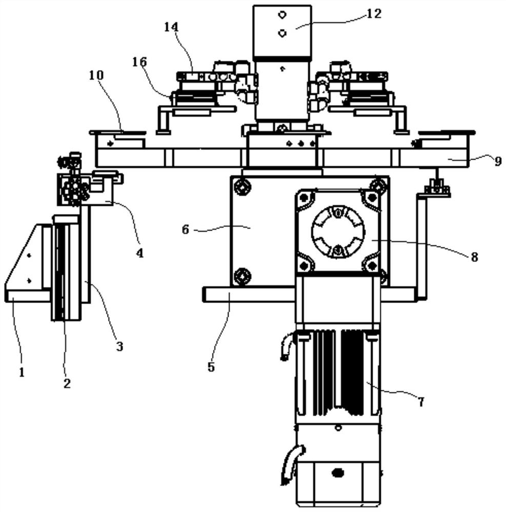
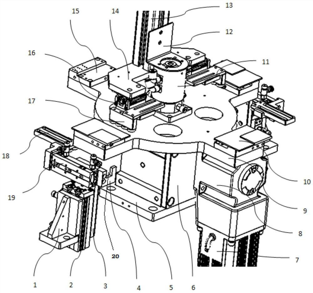
[0023] Such as Figure 1-2 As shown, a special positioning device for a liquid crystal module assembly machine, the device includes:

[0024] The turntable mechanism has a turntable power motor 7, the power output shaft of the turn...


PUM


Abstract

The invention discloses a special positioning device for a liquid crystal module assembling machine, which comprises a turntable mechanism, an air supply path and a backlight four-side mechanical positioning mechanism, wherein the turntable mechanism is provided with a turntable power motor, and a power output shaft of the turntable power motor is connected with an input shaft of a turntable power transmission speed reducer; an output shaft of the turntable power transmission speed reducer is connected with an input shaft of a 90-degree operation cam indexer, the 90-degree operation cam indexer is installed on the turntable mechanism installation base, a four-station turntable is installed on an output shaft of the 90-degree operation cam indexer, four stations are evenly distributed on the four-station turntable, and each station is provided with a negative pressure workbench. According to the mechanism, perfect matching among backlight mechanical positioning, a backlight film tearing and fitting process and backlight material circulation is achieved, the positioning function is separated from stations, the defect that deviation exists in four mechanical positioning due to the fact that the positioning mechanism moves along with the stations is overcome, and the consistency of mechanical positioning on a single station can be guaranteed.

Description

technical field [0001] The invention relates to the field of electronic communication technology LED liquid crystal panel display manufacturing, in particular to a special positioning device for a liquid crystal module assembly machine. Background technique [0002] In the field of LED liquid crystal panel display manufacturing, liquid crystal glass is a display glass that uses liquid crystal control light transmittance technology to achieve color. The backlight is the backplane that reflects behind the liquid crystal glass and provides a light source for lighting. LED LCD display screen is a combination of the two. Liquid crystal module assembly machine is the key equipment for manufacturing liquid crystal display modules. It adopts image alignment system, precision motion control and other technologies, and realizes backlight through technological processes such as glass tear film, backlight tear film, and glass backlight lamination assembly. Electrical and mechanical co...

Claims


Application Information

Patent Timeline
Patent Type & Authority Applications(China)
IPC IPC(8): G02F1/13
CPCG02F1/1303Y02P40/57
Inventor 陈磊李铁吴洪坤菅卫娟任世伟巩天翼白杨潘强强杨宝春
Owner TAIYUAN FENGHUA INFORMATION EQUIP
Why Eureka
Try Eureka