
Novel renewable energy storage reactor and application thereof

A renewable energy and reactor technology, applied in the direction of energy input, electrolysis components, electrodes, etc., can solve the problem of not being able to fundamentally solve the dependence of fossil energy, and achieve the effect of improving the ability to resist carbon deposition and stability

Active Publication Date: 2021-08-31
UNIV OF JINAN
View PDF2 Cites 0 Cited by
  • Summary
  • Abstract
  • Description
  • Claims
  • Application Information

AI Technical Summary

Problems solved by technology

However, CH4 is still a fossil energy and cannot fundamentally solve the dependence on fossil energy

Method used


Image

  • Novel renewable energy storage reactor and application thereof
  • Novel renewable energy storage reactor and application thereof
  • Novel renewable energy storage reactor and application thereof

Examples


Embodiment 1

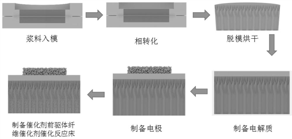
[0042] 36.99 gNiO, 24.66 g (Y 2 o 3 ) 0.08 Zr 0.92 o 2 The powder, 4.3 g of polyethersulfone, 24 g of N-methylpyrrolidone and 0.43 g of polyvinylpyrrolidone were weighed and placed in a ball mill jar, and milled for 48 hours using a planetary ball mill to form a premixed material. The premixed slurry was filtered out and placed in a vacuum stirring device for stirring and exhausting treatment. The vacuum degree was set at -0.08~-0.1MPa, and the stirring and exhausting treatment was performed for 20 minutes to obtain a uniformly mixed electrode slurry without air bubbles. Pour the slurry into the lower mold, place a stainless steel screen with a sieve of 70 μm on the surface of the slurry and allow the slurry to slightly pass through the stainless steel screen, then press the upper mold with upper and lower ends on the screen, and Inject 10mm~15mm thick slurry. Water was used as a flocculant and poured from the top of the slurry to initiate the phase inversion process. Af...

Embodiment 2

[0053] The preparation process of the full battery is the same as the process 2 of Example 1. The full battery is prepared by co-sintering the electrode and the electrolyte, and the electrochemical oxidation of pure ethanol is used to assist in the electrolysis of water.

[0054] Preparation of catalyst for electrolysis of water assisted by electrochemical oxidation of ethanol:

[0055] PD-Gd 0.1 Ce 0.9 o 2 Catalyst precursor: Weigh 0.0444 g Gd(NO 3 ) 3 ·6H 2 O (≥99%), 0.3936 gCe(NO 3 ) 3 ·6H 2 O (≥99%), 4.72 g of N,N-dimethylformamide, and 0.102 g of polyvinylpyrrolidone (PVP, molecular weight 1,300,000) were placed in a beaker and fully dissolved. Weigh 0.0533 g Pd(NO 3 ) 3 2H 2 O (≥99%), dissolved in 1 g of the prepared solution. Then dipped into the support electrode microchannel, sintered at 750 for 2 hours, repeated 2 times.

[0056] Ru-Gd 0.1 Ce 0.9 o 2 Fiber catalyst: Weigh 0.3173 g Gd(NO 3 ) 3 ·6H 2 O (≥99%), 0.1313 gRuCl 3 , 2.7475 g Ce(NO 3 ) 3...


PUM

PropertyMeasurementUnit
thicknessaaaaaaaaaa
thicknessaaaaaaaaaa
thicknessaaaaaaaaaa

Abstract

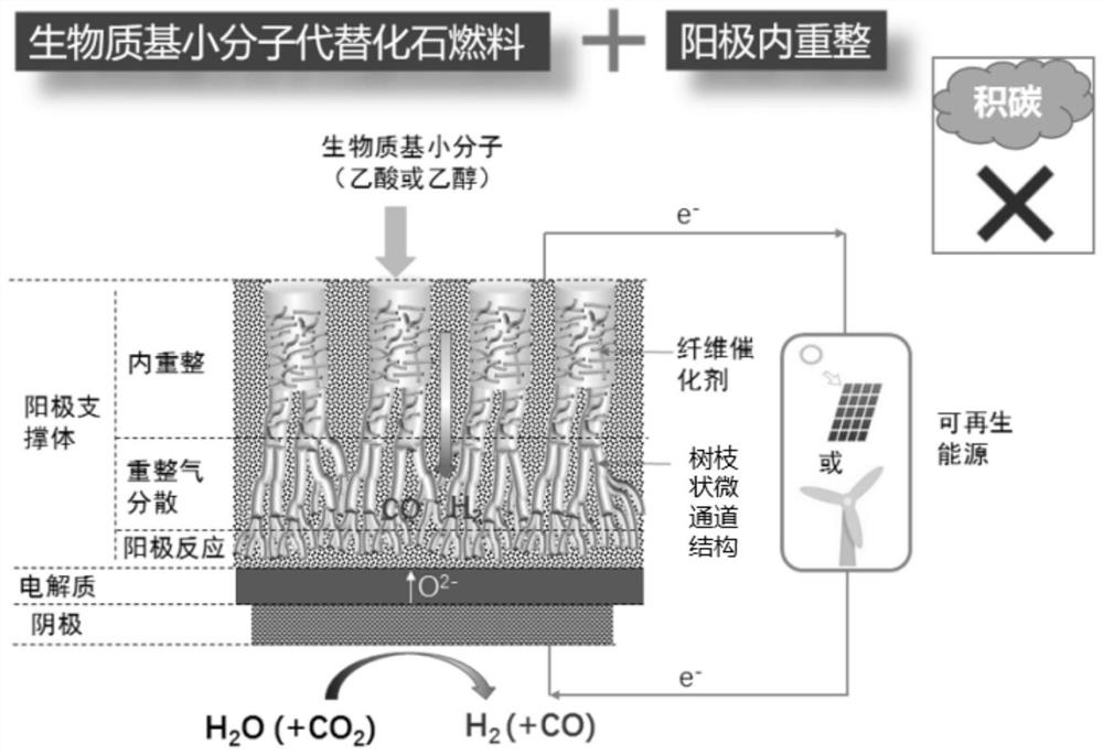
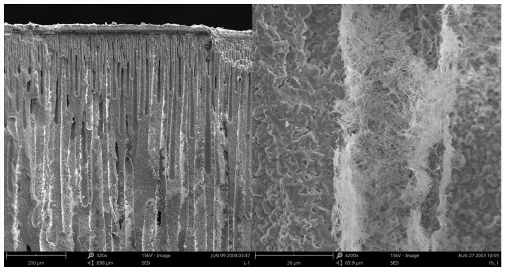
The invention belongs to the technical field of solid oxide electrolytic tanks, and particularly relates to a novel renewable energy storage reactor and application thereof. The renewable energy source reactor is suitable for a solid oxide battery with a cathode support type or anode support type structure. The solid oxide battery can utilize biomass-based small molecules to assist in electrolyzing water, so that efficient storage of renewable energy sources is realized. According to the renewable energy storage reactor developed by the invention, the supporting anode has a micro-channel structure, so that an effective way is provided for rapid diffusion of gas; and the micro-channel is filled with a catalyst and is used as an efficient biomass catalytic reforming reactor, so that the carbon deposition resistance and the electrolysis stability of the battery are improved. Compared with a conventional catalytic biomass water reforming hydrogen production process, the reactor has the advantages that electrolysis can be driven by renewable electric energy, synchronous and efficient storage of the biomass and the renewable electric energy is realized, pure hydrogen is obtained in the cathode chamber, and a hydrogen separation process is omitted.

Description

technical field [0001] The invention belongs to the technical field of solid oxide electrolytic cells, and in particular relates to a novel renewable energy storage reactor and its application. Background technique [0002] Solid oxide electrolysis cell (Solid Oxide Electrolysis Cell, SOEC) technology has the advantages of high energy conversion, flexible fuel, etc., combined with solar energy, wind energy and other renewable energy sources, these renewable energy sources can be converted into clean fuel hydrogen (H 2 ), solving the intermittency and volatility of renewable energy is an indispensable and important part of the new energy structure in the future. Evaluating the operating cost of high-temperature electrolysis from the aspects of equipment, raw materials, and energy and power costs, it is found that energy and power costs account for about 60% of the total operating cost, and reducing power consumption has become the key to the commercial application of high-tem...

Claims


Application Information

Patent Timeline
Patent Type & Authority Applications(China)
IPC IPC(8): C25B11/032C25B11/037C25B11/055C25B11/054C25B1/04
CPCC25B11/032C25B11/037C25B11/055C25B11/054C25B1/04Y02P20/133Y02E60/36
Inventor 董德华刘方升
Owner UNIV OF JINAN
Learn More