
A polishing device for throwing magnetic suction type metal rods

A technology for metal rods and polishing devices, which is applied in the direction of grinding/polishing safety devices, metal processing equipment, grinding/polishing equipment, etc., which can solve the problems of accelerating metal corrosion, affecting coating adhesion and anti-corrosion ability, and low pressure, etc. problems, to achieve the effect of increasing the grinding pressure

Active Publication Date: 2021-10-01
南通英富泰电气科技有限公司
View PDF7 Cites 0 Cited by
  • Summary
  • Abstract
  • Description
  • Claims
  • Application Information

AI Technical Summary

Problems solved by technology

Oxide scale is a layer of dense oxide layer produced when steel is forged and pressed at high temperature. It is usually attached more firmly, but it is more brittle than steel itself, and it is a cathode, which will accelerate metal corrosion.
If these substances are not removed and painted directly, it will inevitably affect the adhesion and anti-corrosion ability of the entire coating.
[0003] However, the polishing devices on the market cannot fully polish the metal rod, and the pressure between the grinding wheel and the rod wall is small, especially for the scale with strong adhesion, it is more difficult to remove, and then simply use grinding It is difficult to ensure that the wheel can achieve a good impurity removal and polishing effect on the outer wall of the bar

Method used


Image

  • A polishing device for throwing magnetic suction type metal rods
  • A polishing device for throwing magnetic suction type metal rods
  • A polishing device for throwing magnetic suction type metal rods

Examples


Embodiment 1

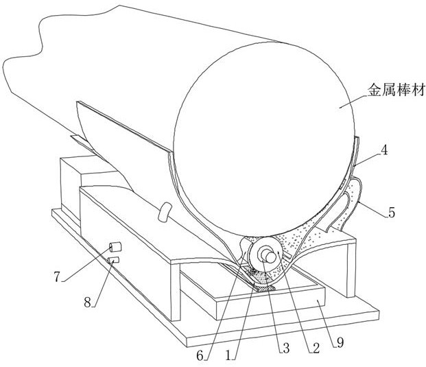
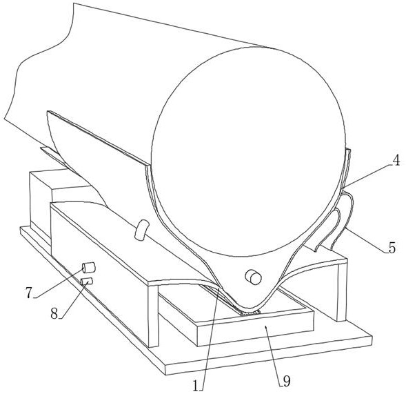
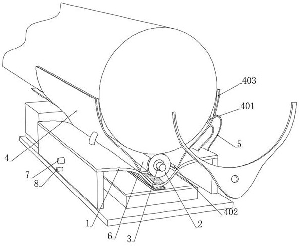
[0045] see Figure 1-3 , a polishing device for throwing magnetic suction metal rods, including a concave arc support 1 installed on a base, a control box is installed at the rear end of the base, and a control box located on a concave arc support is installed on the control box. The magnetic grinding roller 2 above the middle part of the support 1, the magnetic grinding roller 2 is embedded with the inner electromagnetic roller 3 fixedly connected with the control box, and the control system connected with the magnetic grinding roller 2 and the inner electromagnetic roller 3 is installed in the control box, The control system controls the rotation of the magnetic grinding roller 2. The control system controls the speed of the magnetic grinding roller 2 to meet the grinding requirements of different metal bars. The control system controls the internal power supply of the inner electromagnetic roller 3. This is an existing intelligent technology. , without going into too much d...


PUM

PropertyMeasurementUnit
diameteraaaaaaaaaa

Abstract

The invention discloses a polishing device for throwing particles and magnetic suction type metal rods, which belongs to the technical field of grinding processing of metal materials. By setting an inner concave arc support and a pair of deflectors, the magnetic grinding roller is located in the falling temperature cooling part There are several magnetic particles at the top of the falling particle cooling part. When the inner electromagnetic roller is electrified and magnetized, the outer wall of the magnetic grinding roller is attached with magnetism, so that the magnetic particles are attached to the outer wall of the magnetic grinding roller, and the magnetic particles rub against the magnetic grinding roller. Between it and the metal bar, it is beneficial to improve the grinding effect. At the same time, the air supply pipe is used to supply air to the falling particle cooling part, and the gas pushes the magnetic particles that are not magnetically attracted on the magnetic grinding roller to throw on the end wall of the metal bar. On the one hand, it can achieve multi-point impact damage to impurities such as scale, which is beneficial to the subsequent polishing of the magnetic grinding roller. In addition, the magnetic particles are rinsed with water, on the one hand to remove dust, and on the other hand to cool down the grinding end surface.

Description

technical field [0001] The invention relates to the technical field of grinding and processing of metal materials, and more specifically relates to a polishing device for throwing particles and magnetically attracting metal rods. Background technique [0002] Usually, the metal surface will be accompanied by dust, oil, scale, rust, pollutants, salt or loose old paint film, among which scale is the most common but most easily overlooked part. Oxide scale is a layer of dense oxide layer produced during high-temperature forging and pressing of steel. It is usually attached more firmly, but it is more brittle than steel itself, and it is a cathode, which will accelerate metal corrosion. If these substances are not removed and painted directly, it will inevitably affect the adhesion and anti-corrosion ability of the entire coating. [0003] However, the polishing devices on the market cannot fully polish the metal rod, and the pressure between the grinding wheel and the rod wall...

Claims


Application Information

Patent Timeline
Patent Type & Authority Patents(China)
IPC IPC(8): B24B27/033B24B41/06B24B55/02B24B55/06B24B1/00
CPCB24B27/033B24B41/067B24B55/02B24B55/06B24B1/005
Inventor 白海鹰
Owner 南通英富泰电气科技有限公司
Learn More