
Numerical control equipment spindle inner cone grinding device and grinding method of grinding device

A technology of grinding device and numerical control equipment, applied in the direction of grinding device, grinding drive device, grinding machine tool, etc., can solve the problems of damage to the transmission mechanism, fluctuation, uneven force of inner cone loss, etc., to prevent damage to the transmission mechanism, eliminate Impaired accuracy, the effect of eliminating force fluctuations

Pending Publication Date: 2021-09-03
CHENGDU AIRCRAFT INDUSTRY GROUP
View PDF12 Cites 1 Cited by
  • Summary
  • Abstract
  • Description
  • Claims
  • Application Information

AI Technical Summary

Problems solved by technology

[0004] The above-mentioned existing technology realizes the precision grinding of the taper hole of the machine tool spindle, so that the machine tool can quickly restore the machining accuracy, but during the grinding process of the inner cone of the main shaft, the uneven loss of the inner cone will cause force fluctuations, so the above-mentioned equipment may be in operation. Can damage the drive mechanism due to fluctuations

Method used


Image

  • Numerical control equipment spindle inner cone grinding device and grinding method of grinding device
  • Numerical control equipment spindle inner cone grinding device and grinding method of grinding device
  • Numerical control equipment spindle inner cone grinding device and grinding method of grinding device

Examples


Embodiment 1

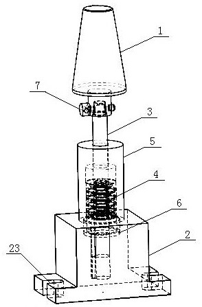
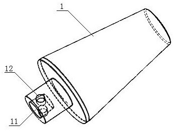
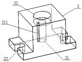
[0034] This embodiment discloses an inner cone grinding device for the main shaft of numerical control equipment. figure 1 , image 3 and Figure 4 , the grinding device includes a grinding knife handle 1 and a fixed base 2, the fixed base 2 is arranged on the workbench, the grinding knife handle 1 is installed on the fixed base 2 by supporting the connecting shaft 3; further, the bottom end of the supporting connecting shaft 3 An installation key 31 is provided, a fixing hole 21 is provided on the fixed base 2, a keyway 211 for limiting the installation key 31 is provided on the inner wall of the fixing hole 21, and the bottom end of the supporting connecting shaft 3 is inserted into the above-mentioned fixing hole 21 and The installation key 31 is located in the keyway 211; further, the fixed base 2 is also provided with a groove 22, the cross section of the groove 22 is circular, the groove 22 is coaxial with the fixing hole 21 and is connected with the fixing hole 21 thr...

Embodiment 2

[0043] This embodiment discloses an inner cone grinding device for the main shaft of numerical control equipment. figure 1 and Figure 5 , on the basis of Embodiment 1, the support connecting shaft 3 is sleeved with a pre-tension spring seat 5, and the pre-tension spring seat 5 is provided with a step hole 51 along the axial direction, which are respectively the first step hole 511 and the second step In the hole 512, the supporting connecting shaft 3 runs through two stepped holes, and the two ends are respectively connected with the grinding handle 1 and the fixed base 2, and the preload spring 4 and the supporting shoulder 32 are all arranged in the second stepped hole 512. The bottom end of the pre-tightening spring seat 5 is provided with an external thread, and the inner wall of the groove 22 is correspondingly provided with an internal thread, and the pre-tightening spring seat 5 is connected with the internal thread on the groove 22 by the external thread, thereby bein...

Embodiment 3

[0051] This embodiment discloses a method for grinding the inner cone of the main shaft of a numerical control equipment. The method is realized by the grinding device in the above embodiment. Apply it on the surface of the grinding tool holder, then move the machine tool so that the inner cone of the main shaft fits the grinding tool holder of the grinding device, manually rotate the main shaft, make the inner cone of the main shaft and the grinding tool holder automatically center and make them match evenly, and finally pass Fix the grinding device on the workbench by fixing the base, start the machine tool, and use the spindle to rotate to grind the inner cone of the spindle and the grinding handle.

[0052] In this implementation, the method of first aligning and then fixing the grinding device is used to realize the grinding of the inner cone of the main shaft. Compared with the prior art, the method of first fixing the grinding device and then using the numerical control ...


PUM


Abstract

The invention relates to the technical field of machining, and discloses a numerical control equipment spindle inner cone grinding device and a grinding method thereof. The numerical control equipment spindle inner cone grinding device comprises a grinding cutter handle and a fixing base, the grinding cutter handle is installed on the fixing base through a supporting connecting shaft, an installation key is arranged at the bottom end of the supporting connecting shaft, and a fixing hole is formed in the fixing base; and the inner side wall of the fixing hole is provided with a key groove used for limiting the installation key, the bottom end of the supporting connecting shaft is inserted into the fixing hole, the installation key is located in the key groove, the fixing base is further provided with a groove, the groove and the fixing hole are coaxial, the groove is communicated with the fixing hole, and the supporting connecting shaft is sleeved with a pre-tightening spring. One end of the pre-tightening spring acts on the bottom face of the groove, and the other end of the pre-tightening spring acts on a supporting shoulder extending out of the supporting connecting shaft in the radial direction. A spindle rotates to enable a spindle inner cone to be matched with a grinding cone so as to achieve grinding, and therefore the precision of the inner cone and the cutter installing matching precision are guaranteed.

Description

technical field [0001] The present application relates to the technical field of mechanical processing, in particular to a grinding device and a grinding method for an inner cone of a spindle of a numerical control equipment. Background technique [0002] In the field of mechanical processing, the spindle is called the "heart" of CNC equipment. The reason is that the precision of the cutting tool clamped by the spindle directly affects the product quality, and the direct factor of the tool assembly accuracy is the cooperation between the spindle inner cone positioning surface and the tool holder. accuracy, but the inner cone of the spindle usually has oil pollution, which will cause pitting and electrolysis on the positioning surface of the spindle inner cone, which intensifies the vibration, extrusion and wear of the spindle inner cone positioning surface and the tool sleeve during the cutting process , resulting in the spindle precision not meeting the process requirements...

Claims


Application Information

Patent Timeline
IPC IPC(8): B24B37/02B24B37/11B24B37/34B24B47/12B24B47/22
CPCB24B37/02B24B37/11B24B37/34B24B47/12B24B47/22
Inventor 罗兴华张伟伟夏远猛李颖周超谢靖超张云周翔
Owner CHENGDU AIRCRAFT INDUSTRY GROUP
Learn More