Ex-situ low-carbon circulating thermal desorption system for polluted soil

A technology of polluted soil and carbon cycle, applied in the restoration of polluted soil, separation method, dispersion particle separation and other directions, can solve the problems of large fossil energy, atmospheric environment pollution, consumption and so on

Inactive Publication Date: 2021-09-10
上海环土环境科技有限公司
View PDF17 Cites 1 Cited by
  • Summary
  • Abstract
  • Description
  • Claims
  • Application Information

AI Technical Summary

Problems solved by technology

This technology uses the heat source of gas combustion to heat the soil, and the heating process will generate CO 2 and other greenhouse gases, and consume a lot of fossil energy
[0003] The Chinese patent discloses: a desorption system for treating industrial volatile organic pollutants, patent application number: 201310452068.9; discloses: a thermal desorption system for ex-situ building piles of polluted soil, patent application number: 202020935132.4; discloses: An in-situ gas thermal desorption organic polluted soil remediation device, patent application number: 202011295600.7; disclosed: a device and method for in-situ thermal desorption of contaminated soil intensified heat addition, patent application number: 202011292771.4; disclosed: used for high High-efficiency and energy-saving ectopic thermal desorption system for high-concentration polluted soil, patent application number: 202010813685.7; disclosed: an in-situ heat conduction desorption system and its process based on steam enhancement, patent application number: 202011257234.6, but in the above comparison documents, During the operation of the thermal desorption system, a large amount of CO will still be generated 2 , leading to pollution of the atmospheric environment, etc., so there is an urgent need for an ex-situ low-carbon cycle thermal desorption system for polluted soil to solve the problem of high energy consumption and large amounts of CO produced by existing thermal desorption systems. 2 The problem

Method used


Image

  • Ex-situ low-carbon circulating thermal desorption system for polluted soil
  • Ex-situ low-carbon circulating thermal desorption system for polluted soil

Examples


Embodiment Construction

[0023] In order to make the purpose, technical solution and advantages of the present application clearer, the technical solution of the present application will be clearly and completely described below in conjunction with specific embodiments of the present application and corresponding drawings. Apparently, the described embodiments are only some of the embodiments of the present application, rather than all the embodiments. Based on the embodiments in this application, all other embodiments obtained by persons of ordinary skill in the art without making creative efforts belong to the scope of protection of this application.

[0024] The technical solutions provided by various embodiments of the present application will be described in detail below in conjunction with the accompanying drawings.

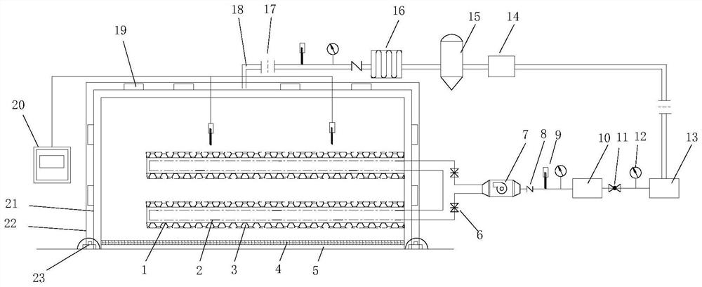
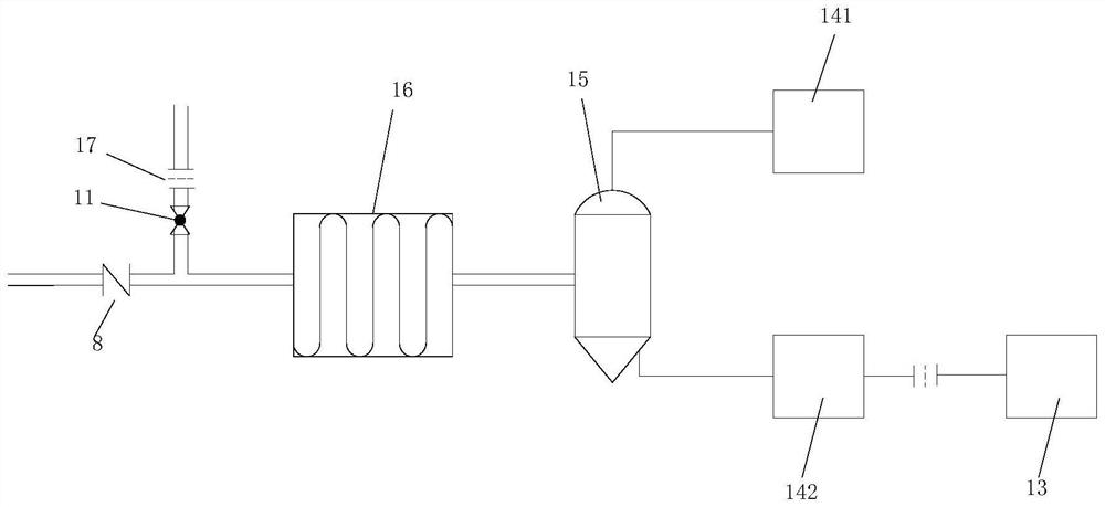
[0025] see Figure 1 to Figure 2, the present invention provides an ectopic low-carbon cycle thermal desorption system for polluted soil, comprising a soil pile, a heating system,...


PUM


Abstract

The invention discloses a ex-situ low-carbon circulation thermal desorption system for polluted soil. The system comprises a soil pile body, a heating system, a heating pipe, an exhaust pipe, a covering heat preservation system, a control system and a tail gas treatment system, an impermeable layer is arranged at the bottom of the soil pile body, and the heating system is arranged on the right side of the pile body. According to the invention, condensed gas and water are separated by the gas-liquid separator, the separated gas enters a gas-phase activated carbon canister, and the separated liquid enters a liquid-phase activated carbon canister. And the gas purified by the gas-phase activated carbon canister enters a nitrogen making machine again to be recycled. A flow meter is arranged between the gas-phase activated carbon canister and a pipeline of the nitrogen making machine, the joints of a breathable film and an impermeable film and the ground are sealed in a mechanical punching mode, the films and sealing strips are arranged at hole forming positions, and screws are fixed on the sealing strips. The impermeable film is laid on the upper portion of the punching position, the edge of the impermeable film is welded to the impermeable film, and a sealed environment is formed to prevent gas from overflowing.

Description

technical field [0001] The present application relates to the technical field, in particular to an ex-situ low-carbon cycle thermal desorption system for polluted soil. Background technique [0002] In recent years, typical organic pollutants such as petroleum hydrocarbons, polycyclic aromatic hydrocarbons, and benzene series have exceeded the standard in the industrial polluted sites left after the relocation of chemical companies. At present, a variety of remediation technologies have been applied to VOC-contaminated sites. Thermal desorption technology is a heat treatment technology that can efficiently remove pollutants in soil. Thermal desorption technologies for contaminated soil are mainly divided into in-situ and ex-situ thermal desorption technologies. In-situ thermal desorption refers to the in-situ heating of the soil in the polluted area, so that the pollutants in it move into the gas phase or liquid phase, and then are captured by the in-situ extraction system...

Claims


Application Information

Patent Timeline
Patent Type & Authority Applications(China)
IPC IPC(8): B09C1/06B08B15/04B01D53/00B01D5/00
CPCB09C1/06B08B15/04B09C1/005B01D5/00B01D53/00
Inventor 吴晓烽佟琛付奕舒王腾
Owner 上海环土环境科技有限公司
Why Eureka
Try Eureka