
Low-contact thermal resistance installation method for high-power power amplifier chip

A power amplifier chip and contact thermal resistance technology, which is applied in welding equipment, auxiliary equipment, metal processing equipment, etc., can solve the problems of large influence of manual operation, difficulty in guaranteeing welding quality, etc.

Active Publication Date: 2021-09-10
NO 54 INST OF CHINA ELECTRONICS SCI & TECH GRP
View PDF11 Cites 0 Cited by
  • Summary
  • Abstract
  • Description
  • Claims
  • Application Information

AI Technical Summary

Problems solved by technology

The advantage is that when the solder is applied thinly and evenly, without bubbles and impurities, and the welding effect is good, the lowest contact thermal resistance can be obtained. The disadvantage is that the operation is difficult and the manual operation has a great influence. Due to the large heat sink of the box body, the solder will Rapid cooling, it is difficult to ensure the quality of welding, so it is difficult to ensure low contact thermal resistance, and it is difficult to ensure the consistency of the temperature of multiple identical chips

Method used


Image

  • Low-contact thermal resistance installation method for high-power power amplifier chip
  • Low-contact thermal resistance installation method for high-power power amplifier chip

Examples


Embodiment Construction

[0028] The present invention will be further described in detail below in conjunction with the accompanying drawings and specific embodiments.

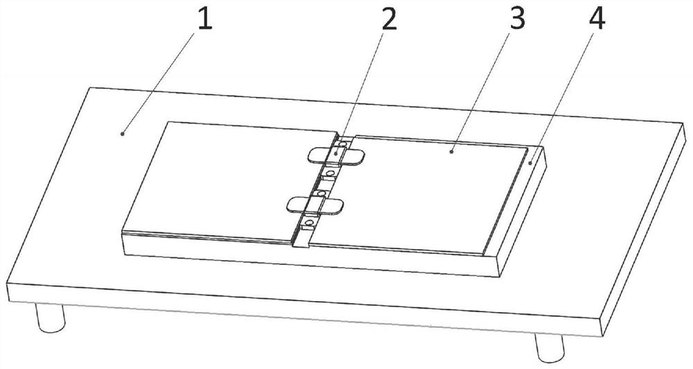
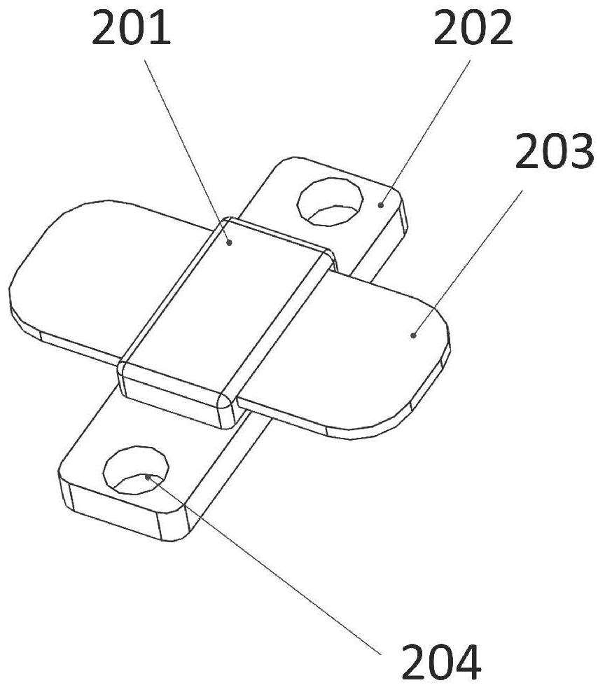
[0029] A method for installing a high-power power amplifier chip with low contact thermal resistance, such as figure 1 As shown, a constant temperature heating platform 1 is used to heat the bottom plate 4 of the metal shielding box, and a high-power power amplifier chip 2 and a printed board 3 are installed on the bottom plate 4 of the metal shielding box. The structure of the high-power power amplifier chip 2 is as follows: figure 2 As shown, it includes a chip case 201 , a metal base 202 , and chip leads 203 .

[0030] The method specifically includes the following steps:

[0031] (101) Mill out a mounting groove on the mounting surface of the high-power power amplifier chip on the bottom plate 4 of the metal shielding box, the depth of the mounting groove is 1mm, and the width is the same as the width of the metal base 202 of t...


PUM


Abstract

The invention discloses a low-contact thermal resistance installation method for a high-power power amplifier chip, and belongs to the technical field of electronic component installation. According to the method, a constant-temperature heating platform is adopted to heat the bottom of a metal shielding box bottom plate, so that the temperature of the metal shielding box bottom plate is uniform, and thus, the melting speed and the cooling speed of soldering tin are uniform, a low-temperature welding wire of 150 DEG C can be used, the welding temperature is controllable, and the soldering tin can be guaranteed to be well melted; and an internal circuit of the chip is prevented from being damaged by an over-high temperature. The method is easy and convenient to operate, controllable in welding time and good in welding quality consistency, and can well guarantee the contact thermal resistance and temperature consistency of a plurality of chips.

Description

technical field [0001] The invention relates to the technical field of electronic component installation, in particular to a method for installing a high-power power amplifier chip with low contact thermal resistance. Background technique [0002] With the rapid development of IC technology, the calorific value of high-power power amplifier chips increases rapidly with the improvement of integration. Temperature control technology and heat dissipation technology have become important factors restricting the further development and reliability of IC chips. The high-power power amplifier chip generates a lot of heat. In order to provide a good heat dissipation effect, it is usually installed directly on the metal shielding box, and the heat is mainly transferred to the metal shielding box through the metal base. There is contact thermal resistance on the contact surface of the two. Under the condition of constant thermal power, the temperature difference of the contact surface...

Claims


Application Information

Patent Timeline
IPC IPC(8): B23K3/00B23K3/08
CPCB23K3/00B23K3/08
Inventor 谢明君
Owner NO 54 INST OF CHINA ELECTRONICS SCI & TECH GRP
Learn More