Spatial light type electro-optical modulator based on phase change material, and manufacturing method thereof

Pending Publication Date: 2021-09-10
HANGZHOU DIANZI UNIV
View PDF3 Cites 2 Cited by
  • Summary
  • Abstract
  • Description
  • Claims
  • Application Information

AI Technical Summary

Problems solved by technology

[0005] The purpose of the present invention is to overcome the problems of inconvenient control of light modulation devices in the prior art, impractical partial phase change methods, and highly restrictive workplaces, and to provide a method that can qu

Method used


Image

  • Spatial light type electro-optical modulator based on phase change material, and manufacturing method thereof
  • Spatial light type electro-optical modulator based on phase change material, and manufacturing method thereof
  • Spatial light type electro-optical modulator based on phase change material, and manufacturing method thereof

Examples


Embodiment

[0037] Such as Figure 1~9 An electro-optic modulation device and its manufacturing method based on phase-change materials as shown:

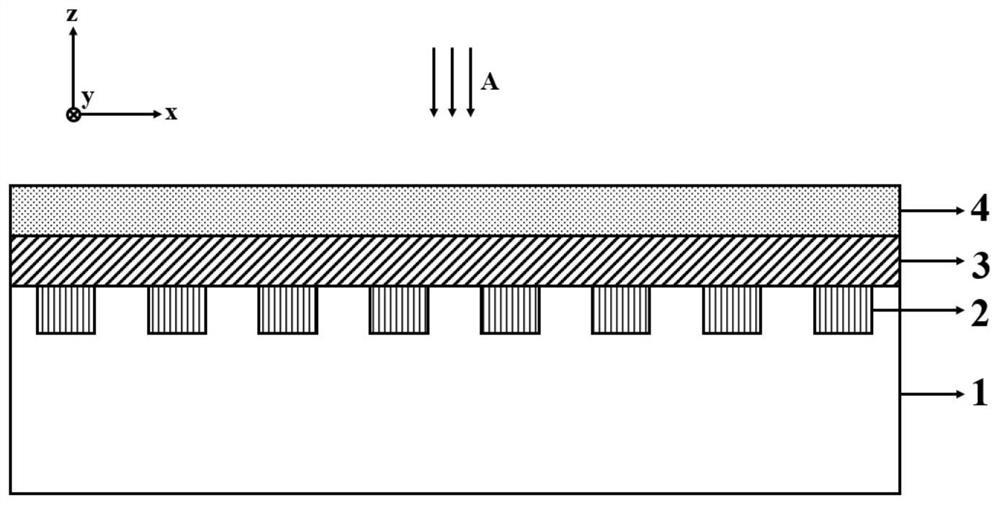
[0038] Such as figure 1 As shown, it is a cross-sectional view of the structural unit of the electro-optic modulation device based on phase-change materials. The cross-sectional structure is the substrate 1, the bottom metal grating layer 2, the amorphous phase-change layer 3 and the cover layer 4 from bottom to top, and the plane wave A is vertical incident into the device.

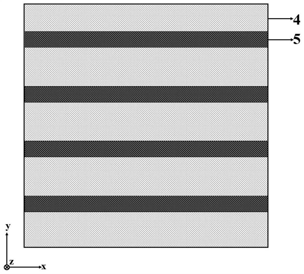
[0039] Such as figure 2 As shown, it is a top view of the structural unit of the electro-optic modulation device based on phase change materials. The period of the top metal grating layer 5 is different from that of the bottom metal grating layer 2. In one embodiment of the present invention, the period of the top metal grating layer 5 is 1000 nm. electrode. The bottom metal grating layer 2 has a double grating structure with a period of 500 nm as the bottom discrete...


PUM

PropertyMeasurementUnit
Thicknessaaaaaaaaaa
Widthaaaaaaaaaa

Abstract

The invention discloses a spatial light type electro-optical modulator based on a phase change material, and a manufacturing method thereof. The electro-optical modulator is formed by a multi-layer composite structure comprising a substrate, a lower electrode layer, a phase change layer, an upper electrode layer and a covering layer, and the upper electrode layer and the lower electrode layer respectively comprise N-bit metal micro-nano gratings and M-bit metal micro-nano gratings which are regularly arranged as electrodes and light field regulation units of the modulator. By controlling the bias voltage of the upper electrode and the lower electrode, the phase change material forms phase change areas with different crystallization degrees, so that the optical dielectric constant is obviously changed, and the reflected light and the resonance absorption peak of the modulator are dynamically electrically modulated. The modulator disclosed by the invention can realize spatial light modulation with N * M area array units, and the working frequency band is positioned in a middle infrared band of 3-10 [mu]m. When the phase change material is in an amorphous state, the device can realize perfect absorption close to 100%; and when the amorphous state and the crystalline state are converted, the modulation depth of about 80% is realized. Not only can the dynamic regulation and control of a perfect absorption peak be realized, but also the dynamic amplitude regulation and control of spatial incident light can be realized.

Description

technical field [0001] The invention relates to the technical field of electro-optic modulators, in particular to a spatial-optic electro-optic modulation device based on phase-change materials and a manufacturing method thereof. Background technique [0002] Non-volatile phase change materials are a new class of adjustable materials with at least two crystalline phases, amorphous and crystalline, which can be achieved through temperature induction, pressure induction, voltage induction, and laser pulse induction. The dynamic adjustment of the crystal phase between states changes its physical properties in terms of force, heat, electricity, and light. Due to the significant difference in atomic arrangement and electronic structure between amorphous and crystalline phase change materials, there are great differences in optical properties (dielectric constant) and electrical properties (conductivity). For materials such as graphene, transparent conductive oxides, and lithium ...

Claims


Application Information

Patent Timeline
IPC IPC(8): G02F1/03
CPCG02F1/0316G02F1/0327Y02P70/50
Inventor 刘孝凯胡鑫陈迎鑫张鉴张雪峰
Owner HANGZHOU DIANZI UNIV
Why Eureka
Try Eureka