Carbide slag slurry clear liquid recycling treatment system and treatment process

A processing system and technology of calcium carbide slag slurry, which is used in the petroleum industry, filtration circuit, and removal of generator residues, etc. issues of time

Active Publication Date: 2021-09-14
陕西煤业化工集团神木电化发展有限公司
View PDF4 Cites 1 Cited by
  • Summary
  • Abstract
  • Description
  • Claims
  • Application Information

AI Technical Summary

Problems solved by technology

[0003] (1) In the process of recovering calcium carbide slurry, since carbide slurry is often in a solid-liquid mixed state, it is difficult to keep the container for storing carbide slurry in a relatively sealed state, which increases the possibility of seepage and leakage of calcium carbide slurry Probability, and it is difficult to disperse and flatten the carbide slurry in the solid-liquid mixed state, which reduces the degree of separation between impurities and clear liquid, and increases the time required for static separation of carbide slurry;
[0004] (2) In the process of recycling calcium carbide slag slurry, it is difficult to quickly remove and separate the floating impurities above the clear liquid after the solid-liquid separation of the calcium carbide slag slurry, and it is easy to cause fluctuations in the clear liquid during the process of removing floating impurities. The removal speed of floating impurities and the clarity of the clear liquid are reduced, and it is also difficult to separate the clear liquid from the solid impurities after the calcium carbide slurry has been allowed to stand, which increases the probability of disturbing the solid slag at the bottom during the extraction of the clear liquid , reduces the clarity of the clear liquid, and it is more difficult to discharge the solid residue accumulated at the bottom after the clear liquid is discharged, which increases the work intensity of the workers' removal and collection operations

Method used


Image

  • Carbide slag slurry clear liquid recycling treatment system and treatment process
  • Carbide slag slurry clear liquid recycling treatment system and treatment process
  • Carbide slag slurry clear liquid recycling treatment system and treatment process

Examples


Embodiment Construction

[0034] In order to make the technical means realized by the present invention, creative features, goals and effects easy to understand, the following combination Figure 1 to Figure 8 , to further elaborate the present invention.

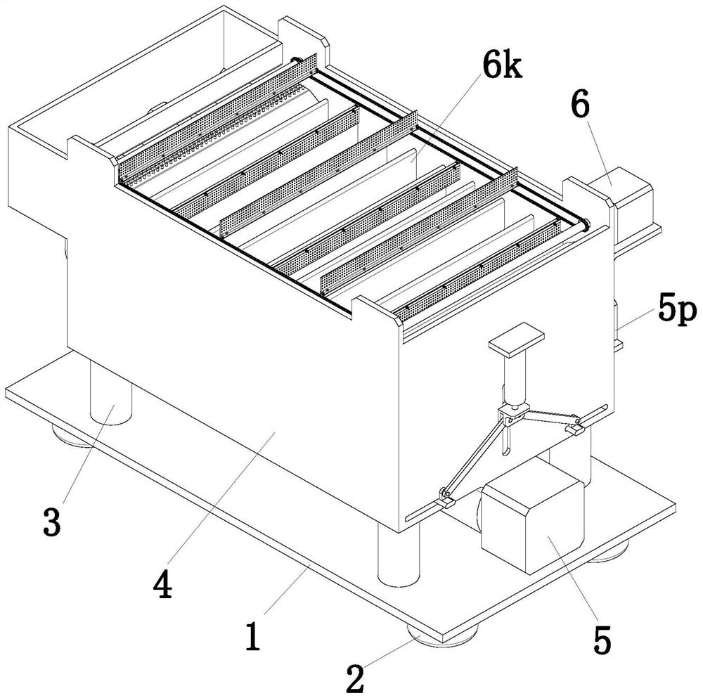
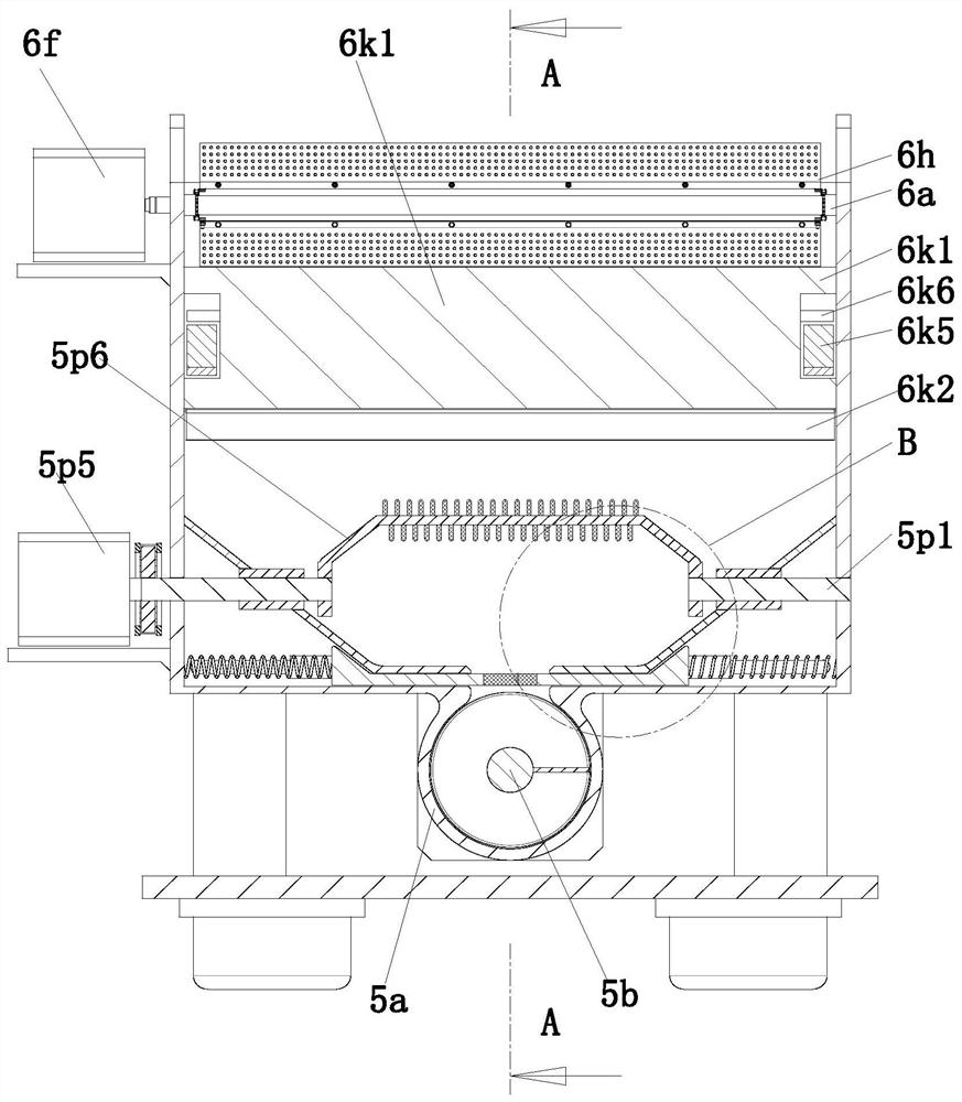
[0035] A recovery and reuse treatment system for calcium carbide slag clear liquid, comprising an installation base plate 1, support feet 2, support columns 3, recovery box 4, mixing mechanism 5 and impurity removal mechanism 6, the corners around the lower end of the installation base plate 1 are uniform Support feet 2 are installed, and support columns 3 are evenly installed at the corners around the upper end surface of the installation base plate 1. The upper end of the support column 3 is equipped with a recovery box 4, and the inner upper end of the recovery box 4 is equipped with an impurity removal mechanism 6. A mixing mechanism 5 is installed at the inner lower end.

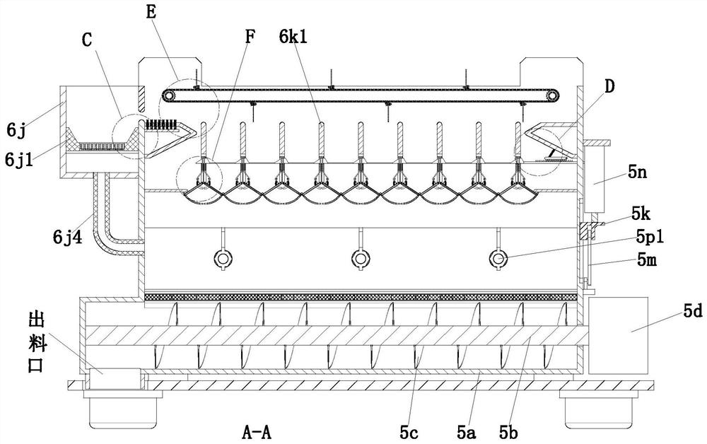
[0036] The mixing mechanism 5 includes a blanking cylinder 5a, a blanki...


PUM


Abstract

The invention provides a carbide slag slurry clear liquid recycling treatment system and a treatment process. The carbide slag slurry clear liquid recycling treatment system comprises a mounting bottom plate, supporting legs, supporting columns, a recycling box, a mixing mechanism and an impurity removal mechanism, and can solve the problems that a container for containing accumulated carbide slag slurry is difficult to be in a relatively sealed state during the carbide slag slurry clear liquid recycling treatment operation, the probability of permeation and liquid leakage of the carbide slag slurry is increased, the carbide slag slurry in a solid-liquid mixed state is difficult to disperse and flatten, the separation degree between impurities and clear liquid is reduced, floating impurities above the clear liquid are difficult to remove and separate quickly after solid-liquid separation of the carbide slag slurry, and solid residues accumulated at the bottom are more difficult to discharge synchronously after the clear liquid is discharged.

Description

technical field [0001] The invention relates to the technical field of calcium carbide slag slurry treatment, in particular to a recovery and reuse treatment system and treatment process for clear liquid of calcium carbide slag slurry. Background technique [0002] Calcium carbide slag is the waste residue with calcium hydroxide as the main component after hydrolysis of calcium carbide to obtain acetylene gas; acetylene (C2H2) is one of the important raw materials in the basic organic synthesis industry, and calcium carbide (CaC2) is used as raw material to produce acetylene by adding water (wet method) The process is simple and mature, and currently accounts for a large proportion in our country; adding water to 1 ton of calcium carbide can generate more than 300 kg of acetylene gas, and at the same time generate 10 tons of industrial waste liquid with a solid content of about 12%, commonly known as calcium carbide slurry; calcium carbide slag can be used instead of limeston...

Claims


Application Information

Patent Timeline
Patent Type & Authority Applications(China)
IPC IPC(8): B01D33/01B01D33/46B01D33/80B01D36/04B01D37/04B01F15/00B01F7/08C10H21/16C10H21/00
CPCB01D33/0158B01D33/461B01D33/801B01D36/04B01D37/04C10H21/16C10H21/00
Inventor 胡瑞林
Owner 陕西煤业化工集团神木电化发展有限公司
Why Eureka
Try Eureka