Ionization type gas sensor and preparation method thereof

A gas sensor and ionization technology, applied in instruments, scientific instruments, and material analysis through electromagnetic means, can solve the problems of high-density current oxidation and degradation of carbon nanotubes

Active Publication Date: 2021-09-14
SHANGHAI AEROSPACE SCI & IND ELECTRIC APPLIANCE RES INST +3
View PDF15 Cites 0 Cited by
  • Summary
  • Abstract
  • Description
  • Claims
  • Application Information

AI Technical Summary

Problems solved by technology

However, carbon nanotubes are easily oxidized and degraded by the high density current induced by the breakdown voltage

Method used


Image

  • Ionization type gas sensor and preparation method thereof
  • Ionization type gas sensor and preparation method thereof
  • Ionization type gas sensor and preparation method thereof

Examples


Embodiment 1

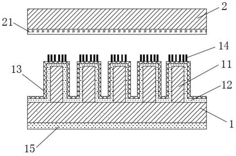
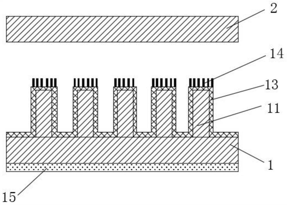
[0041] An ionization gas sensor, comprising a first electrode plate 1 and a second electrode plate 2, the material of the first electrode plate 1 is a silicon wafer, and a layer of conductive metal is sputtered on the side of the first electrode plate 1 away from the second electrode plate 2 Thin film 15, the material of conductive metal thin film 15 is gold; The second electrode plate 2 is a planar electrode;

[0042]The electrode array 11 is provided on the side of the first electrode plate 1 facing the second electrode plate 2 , and a layer of copper film 13 is provided on the upper surface of the electrode array 11 , and the thickness of the copper film 13 is 620 nm. The upper surface of the copper film 13 is provided with metal oxide nanowires 14, and the metal oxide nanowires 14 are CuO nanowires.

[0043] A preparation method of an ionized gas sensor, the method steps are as follows:

[0044] S1: Sputter a layer of uniform conductive metal film on the side of the silic...

Embodiment 2

[0051] An ionization gas sensor, comprising a first electrode plate 1 and a second electrode plate 2, the material of the first electrode plate 1 is a silicon wafer, and a layer of conductive metal is sputtered on the side of the first electrode plate 1 away from the second electrode plate 2 Thin film 15, the material of conductive metal thin film 15 is gold; The second electrode plate 2 is a planar electrode;

[0052] An electrode array 11 is provided on the side of the first electrode plate 1 facing the second electrode plate 2 , and a layer of copper film 13 is provided on the upper surface of the electrode array 11 ; the thickness of the copper film 13 is 620 nm.

[0053] The upper surface of the copper film 13 is provided with metal oxide nanowires 14, and the metal oxide nanowires 14 are CuO nanowires; the second electrode plate 2 is sputtered with an electrode film 21 facing the side of the first electrode plate 1. The material is molybdenum.

[0054] A preparation met...

Embodiment 3

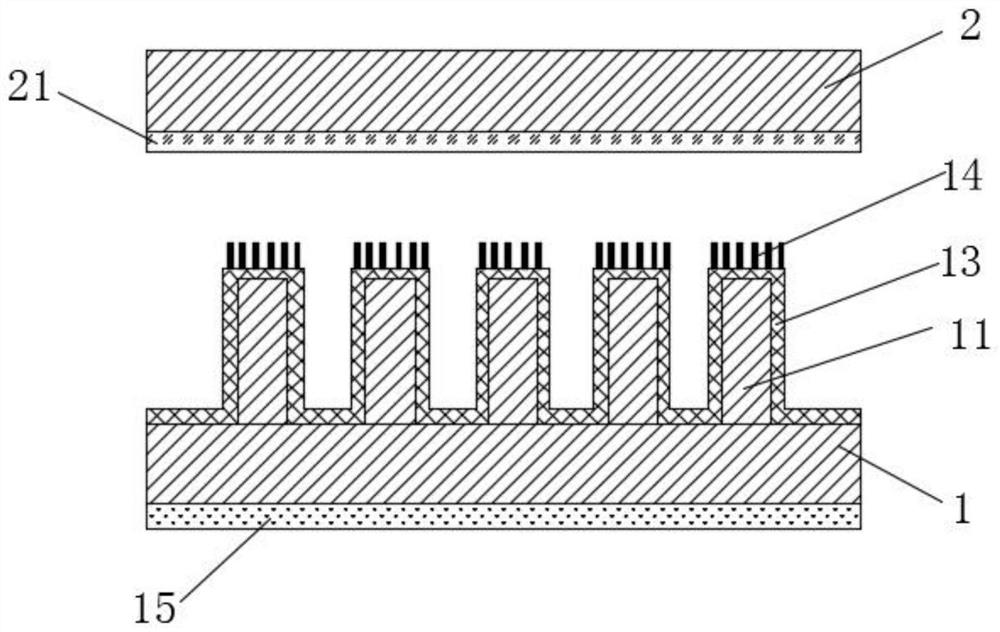
[0063] An ionization gas sensor, comprising a first electrode plate 1 and a second electrode plate 2, the material of the first electrode plate 1 is a silicon wafer, and a layer of conductive metal is sputtered on the side of the first electrode plate 1 away from the second electrode plate 2 Film 15, the material of conductive metal film 15 is silver; the second electrode plate 2 is a plane electrode;

[0064] The electrode array 11 is provided on the side of the first electrode plate 1 facing the second electrode plate 2 , and a layer of copper film 13 is provided on the upper surface of the electrode array 11 , and the thickness of the copper film 13 is 620 nm.

[0065] The upper surface of the copper film 13 is provided with metal oxide nanowires 14, and the metal oxide nanowires 14 are CuO nanowires; the second electrode plate 2 is sputtered with an electrode film 21 facing the side of the first electrode plate 1. The material is chrome.

[0066] A preparation method of a...


PUM

PropertyMeasurementUnit
electron work functionaaaaaaaaaa

Abstract

The invention discloses an ionization type gas sensor which comprises a first electrode plate and a second electrode plate, a layer of conductive metal film is sputtered on one surface, far away from the second electrode plate, of the first electrode plate, and an electrode array is arranged on one surface, facing the second electrode plate, of the first electrode plate. The gas sensor is characterized in that at least one layer of metal film is arranged on the upper surface of the electrode array, a metal oxide nanowire is arranged on the upper surface of the metal film, an electrode film is sputtered on one surface, facing the first electrode plate, of the second electrode plate, and the distance between the first electrode plate and the second electrode plate is 20-400 microns. The gas sensor is simple in preparation process, good in stability, low in breakdown voltage and suitable for commercial production.

Description

technical field [0001] The invention relates to the technical field of nano-device preparation, in particular to a low breakdown voltage ionization gas sensor based on copper oxide nanowires and a preparation method. Background technique [0002] Adsorption gas sensors usually work on the principle of measuring the change in the electrical response of the sensing device when gas molecules are adsorbed on the surface of a sensitive material. Since the adsorption of different gases may elicit similar electrical responses, chemisorption gas sensors often suffer from the difficulty of measuring selectivity. On the other hand, adsorption-type gas sensors have greater difficulty in detecting gases with low adsorption energy, such as noble gases. In addition, some adsorption gas sensors work at higher temperatures. [0003] In order to overcome many problems of conventional chemical adsorption gas sensors, it is a good choice to introduce physical ionization gas sensors. Since m...

Claims


Application Information

Patent Timeline
Patent Type & Authority Applications(China)
IPC IPC(8): G01N27/70
CPCG01N27/70
Inventor 刘晓东王旭赵婷婷刘海候小强孔令伟张艳朱文欢
Owner SHANGHAI AEROSPACE SCI & IND ELECTRIC APPLIANCE RES INST
Why Eureka
Try Eureka