Simulation system and method for laser cutting production line

A technology of laser cutting and simulation system, which is applied in the direction of manufacturing computing system, data processing application, comprehensive factory control, etc., and can solve the problems of low control logic test efficiency and poor intuition

Active Publication Date: 2021-09-14
HANS LASER SMART EQUIP GRP CO LTD +1
View PDF9 Cites 0 Cited by
  • Summary
  • Abstract
  • Description
  • Claims
  • Application Information

AI Technical Summary

Problems solved by technology

[0005] The present invention provides a simulation system and method for a laser cutting production line to solve the technical problems existing in t

Method used


Image

  • Simulation system and method for laser cutting production line
  • Simulation system and method for laser cutting production line
  • Simulation system and method for laser cutting production line

Examples


no. 1 example

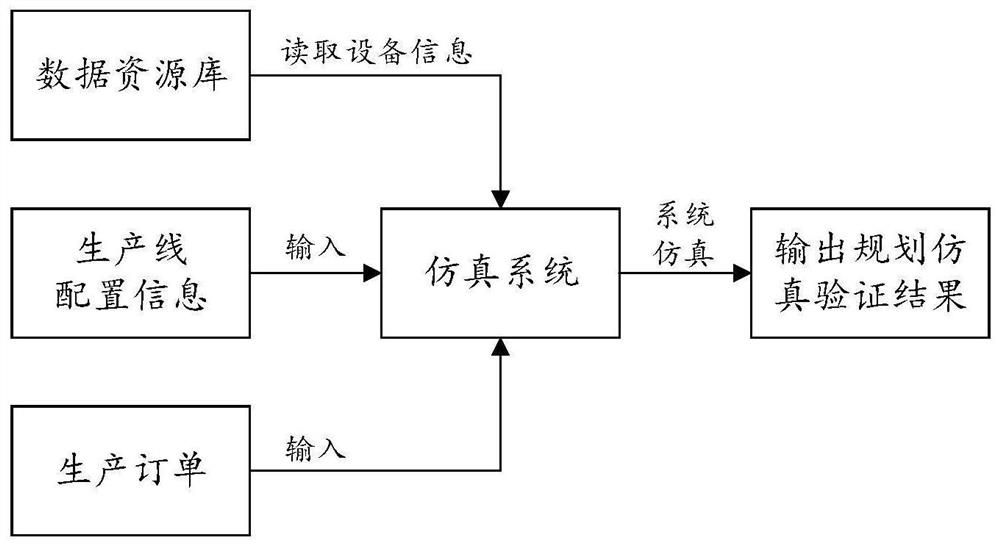
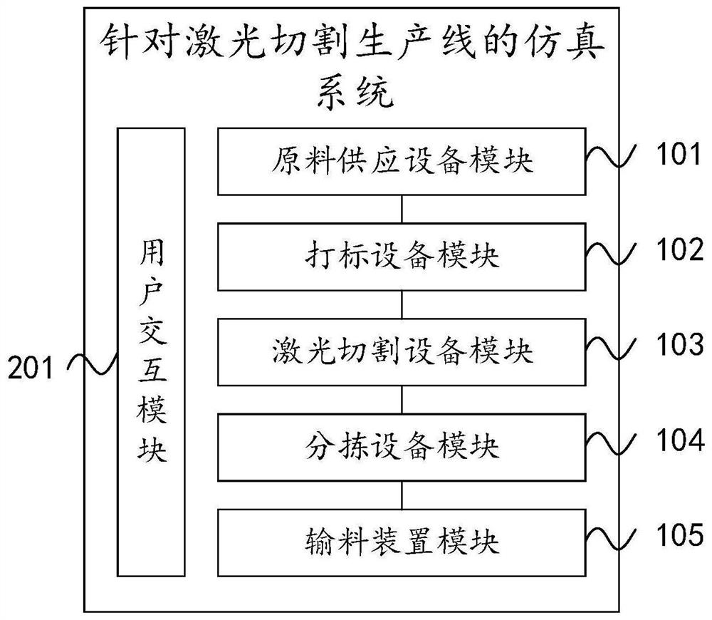
[0050] Aiming at the problems of low efficiency and poor intuitiveness in planning, verifying, and controlling logic testing of a real laser cutting production line in the prior art, this embodiment provides a simulation system for a laser cutting production line. It should be noted that the simulation It is to establish the same system model as the real system in the computer, and avoid the cost caused by the real system experiment through the simulation experiment. Based on this, the simulation system principle of this embodiment is as follows figure 1 shown. Its structure is as figure 2 As shown, including a user interaction module 201 and a simulation module;

[0051] The user interaction module 201 is used to send the laser cutting production line configuration information and production order information input by the user to the simulation module, and output the production line planning simulation result information to the user after the simulation ends;

[0052] The ...

no. 2 example

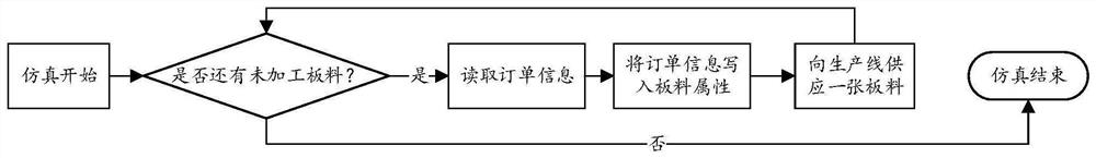
[0083] see Figure 12 , the present embodiment provides a simulation method for a laser cutting production line, including:

[0084] Receive the laser cutting production line configuration information and production order information input by the user, store the received laser cutting production line configuration information in the production line configuration table, and store the received production order information in the production planning task table; among them, the laser cutting production line Configuration information includes the model and planned location of each device in the laser cutting production line; production order information includes sheet metal processing time and marking time;

[0085] Read the parameter information of each equipment in the laser cutting production line in the preset data resource library, and generate the corresponding simulation model of the laser cutting production line according to the configuration information of the laser cuttin...


PUM


Abstract

The invention discloses a simulation system and method for a laser cutting production line. The system comprises a user interaction module and a simulation module. The user interaction module is used for sending production line configuration information and production order information input by a user to the simulation module and outputting simulation result information to the user after simulation is finished; the simulation module is used for generating a corresponding production line simulation model according to the production line configuration information, simulating the laser cutting machining process through the production line simulation model according to the production order information, and sending a simulation result to the user interaction module after simulation is finished; wherein the production line configuration information comprises the model and the planned position of each device in the production line; the production order information comprises plate processing time and marking time. The method is suitable for laser cutting production line planning, production line planning and verification cost can be reduced, and production line design efficiency is improved.

Description

technical field [0001] The invention relates to the technical field of production line simulation, in particular to a simulation system and method for a laser cutting production line. Background technique [0002] Laser Cutting Production System (Laser Cutting Production System) is a fully automatic production line with laser cutting equipment cutting and processing sheets as the core. Its structure includes laser cutting equipment, raw material supply equipment, marking equipment, feeding device, unloading device, Sorting equipment, exchange tables, tracks. Among them, the raw material supply equipment provides the sheet to be processed for the production line; the marking equipment performs marking on the sheet; the laser cutting equipment cuts and processes the sheet; the sorting equipment sorts and cuts the sheet for the production line; The device moves horizontally on the track to transport sheets between the raw material supply equipment, marking equipment and laser ...

Claims


Application Information

Patent Timeline
IPC IPC(8): G06Q10/06G06Q50/04
CPCG06Q10/067G06Q10/0631G06Q10/06316G06Q50/04Y02P90/30
Inventor 赵宁付卓睿
Owner HANS LASER SMART EQUIP GRP CO LTD
Why Eureka
Try Eureka