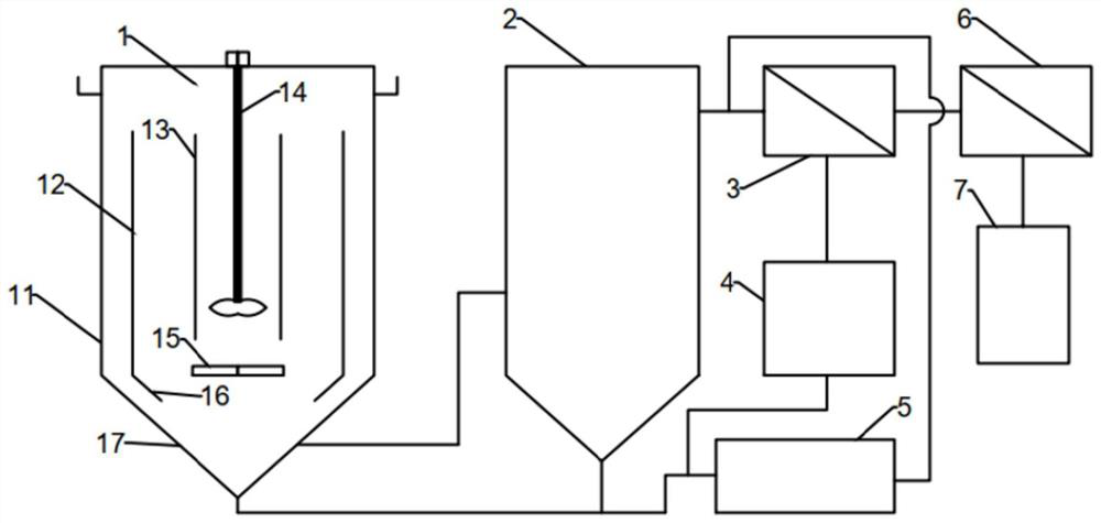
Drilling wastewater treatment system

A technology for treating system and drilling wastewater, which is applied in mining wastewater treatment, water/sewage treatment, heating water/sewage treatment, etc. It can solve the problems of difficult water quality, standard discharge, high treatment cost, etc., and achieve low oil content, complete separation, The effect of high deoiling efficiency

Pending Publication Date: 2021-09-21
南通固润环保科技有限公司
View PDF6 Cites 0 Cited by
  • Summary
  • Abstract
  • Description
  • Claims
  • Application Information

AI Technical Summary

Problems solved by technology

[0002] Drilling wastewater is mainly a multi-phase stable suspension composed of clay, drilling cuttings, weighting materials, chemical additives, inorganic salts, and oil. Biological and chemical methods are more difficult to deal with
Drilling wastewater also has the characteristics of wide distribution area, many points and wide areas, and the number of each point is small, so centralized treatment is difficult and costly
The above characteristics determine that the drilling wastewater is very difficult to treat. Conventional treatment methods are difficult to make the water quality discharge up to the standard. At present, the main disposal method is to re-inject into the ground, but because the removal of harmful substances in the wastewater is not ideal, especially COD seriously exceeds the standard, it will be harmful groundwater pollution
[0003] Although the physical evaporation process is effective in treating oil drilling wastewater, it needs to consume a lot of heat or electricity, and the processing cost is very high. At present, the energy consumption of energy-saving mechanical compression evaporation proce

Method used


Image

  • Drilling wastewater treatment system

Examples


Embodiment 1

[0044] A drilling wastewater, COD: 1750mg / L, pH8.6, TP: 1.1mg / L, ammonia nitrogen 14.0mg / L, chloride ion content: 8450mg / L, suspended solids: 1648mg / L, oil content: 179mg / L;

[0045]The residence time in the internal circulation reactor is 20min, the effluent COD: 1140mg / L, pH7.5, TP: 0.9mg / L, ammonia nitrogen 0.6mg / L, chloride ion content: 7648mg / L, suspended solids: 145mg / L, oil content 31mg / L;

[0046] The effluent from the internal circulation reactor is transported to the settling tank for a residence time of 1.5h. The effluent of the settling tank has COD: 861mg / L, pH6.9, TP0.5mg / L, chloride ion content: 7348mg / L, and suspended solids: 11mg / L;

[0047] The effluent of the sedimentation tank enters the ultrafiltration device, and the ultrafiltration effluent COD: 164mg / L, pH7.1, TP: 0.2mg / L, ammonia nitrogen 0.1mg / L, chloride ion content: 11100mg / L; the ultrafiltration effluent enters the evaporation device for salinization evaporative crystallization treatment, and tran...

Embodiment 2

[0051] On the basis of Example 1, the oxidation tank was replaced by an electrocatalytic oxidation tank, and the chlorine ions in the ultrafiltered concentrated water were electrocatalyzed to form hypochlorite to oxidize and degrade the organic matter in the wastewater.

[0052] The electrocatalytic cell is equipped with mesh cathode and anode plates, and the anode is Ti / SnO 2 And iron plate, the cathode catalytic electrode is Ti metal electrode, the working current intensity is 10-30 amperes / ㎡ DC; the COD concentration of the effluent is reduced to 92.6mg / L, and the effluent of the electrocatalytic cell is returned to the ultrafiltration device.


PUM


Abstract

The invention relates to a drilling wastewater treatment system which comprises an internal circulation reactor (1), a sedimentation tank (2), an ultrafiltration device (3), an oxidation tank (4) and a plate-and-frame filter (5). The circulating reactor (1) comprises a shell (11), an outer cylinder (12), an inner cylinder (13), a stirring device (14), an aeration head (15), a folded plate (16) and a conical bottom (17). The shell (11) is of a barrel-shaped structure, and the bottom of the barrel-shaped structure is connected with a cone bottom (17). A drain pipe is arranged at the middle upper part of the cone bottom (17) and/or the shell (11) and is communicated with the sedimentation tank (2), and a drain pipe is arranged at the middle upper part of the sedimentation tank (2) and is communicated with the ultrafiltration device (3). A concentrated drain pipe of the ultrafiltration device (3) is communicated with the oxidation pond (4), and the oxidation pond (4) is communicated with the plate-and-frame filter (5). And a stirring device (14) is arranged on a central shaft of the cylindrical structure. The drilling wastewater treatment system can improve the deoiling efficiency.

Description

technical field [0001] The invention belongs to the field of wastewater treatment, and in particular relates to a drilling wastewater treatment system. Background technique [0002] Drilling wastewater is mainly a multi-phase stable suspension composed of clay, drilling cuttings, weighting materials, chemical additives, inorganic salts, and oil. It is difficult to deal with biological and chemical methods. Drilling wastewater also has the characteristics of wide distribution area, many points and wide areas, and the number of each point is small, so centralized treatment is difficult and costly. The above characteristics determine that the drilling wastewater is very difficult to treat. Conventional treatment methods are difficult to make the water quality discharge up to the standard. At present, the main disposal method is to re-inject into the ground, but because the removal of harmful substances in the wastewater is not ideal, especially COD seriously exceeds the standa...

Claims


Application Information

Patent Timeline
IPC IPC(8): C02F9/10C02F103/10
CPCC02F9/00C02F1/02C02F1/24C02F1/36C02F1/40C02F1/001C02F1/444C02F1/441C02F1/722C02F1/725C02F1/4672C02F1/5236C02F2103/10C02F2303/14
Inventor 何力波周凯旋
Owner 南通固润环保科技有限公司
Why Eureka
Try Eureka