
Method for establishing SOFC/SOEC electrode microstructure electrochemical model

A technology of microstructure and method of establishment, applied in CAD numerical modeling, design optimization/simulation, special data processing applications, etc., can solve the problems of inability to accurately identify three-phase boundary lines, Jacobian matrix singularity, prone to error reporting, etc.

Active Publication Date: 2021-09-21
HARBIN INST OF TECH SHENZHEN GRADUATE SCHOOL
View PDF4 Cites 2 Cited by
  • Summary
  • Abstract
  • Description
  • Claims
  • Application Information

AI Technical Summary

Problems solved by technology

Previous scholars have used the LBM method to perform simulations. However, although this method can predict the electrochemical performance of electrodes relatively accurately, the calculation cost is relatively expensive, and subsequent coupling with other physical fields will be very difficult.
The finite element method is a relatively good alternative. However, no scholars have been able to use finite element technology to systematically study the electrochemical performance of SOFC / SOEC electrodes. The main reason is that the simulation process will encounter the following difficulties: 1) It is impossible to accurately identify the Stabilize the three-phase boundary line TPB at the intersection of zirconia, nickel and gaseous phases, and the software itself cannot identify TPBs that are invalid for the reaction; 2) When dealing with the electrochemical coupling of diffusion equations, errors are prone to occur, the main reason is that iterative in the solver The calculation process encounters the singularity of the Jacobian matrix

Method used


Image

  • Method for establishing SOFC/SOEC electrode microstructure electrochemical model
  • Method for establishing SOFC/SOEC electrode microstructure electrochemical model
  • Method for establishing SOFC/SOEC electrode microstructure electrochemical model

Examples


Embodiment Construction

[0046] The specific implementation of the present invention will be further described in detail below in conjunction with the accompanying drawings and examples, but it is not limited thereto. Any modification or equivalent replacement of the technical solution of the present invention without departing from the spirit and scope of the technical solution of the present invention is acceptable. Should be included in the protection scope of the present invention.

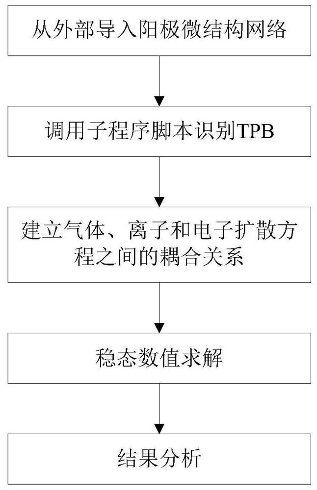
[0047] In view of the deficiencies in the prior art, the present invention proposes a method for establishing an electrochemical model of the SOFC / SOEC electrode microstructure, the flow chart is as follows figure 1 As shown, it mainly includes the following steps:

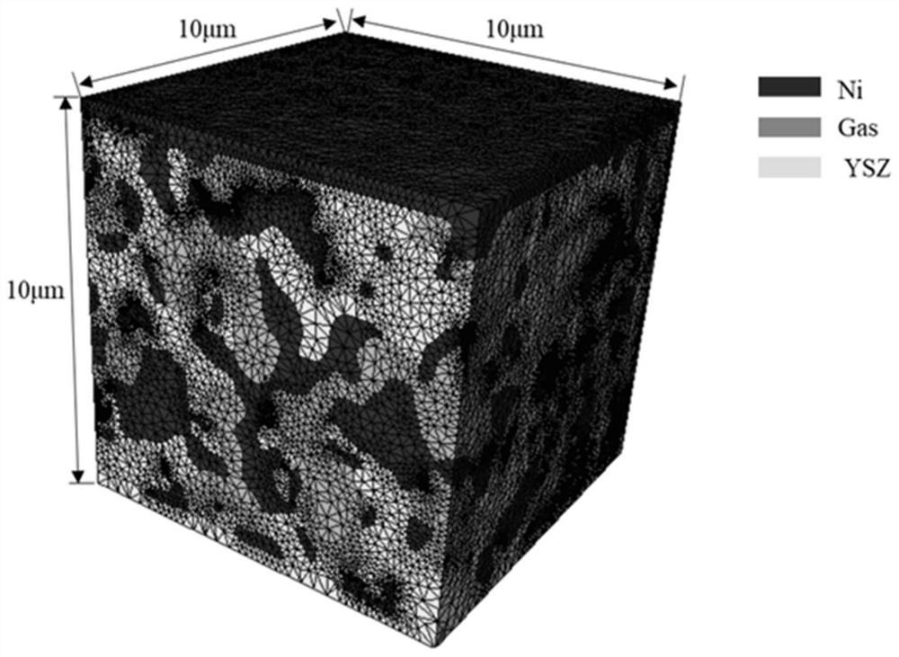
[0048]Step S1, use COMSOL finite element software to import the electrode microstructure network from the outside, call the subroutine script to identify TPB, and identify yttria-stabilized zirconia (YSZ), nickel (Ni) and gaseous phase (Gas) in the grid c...


PUM


Abstract

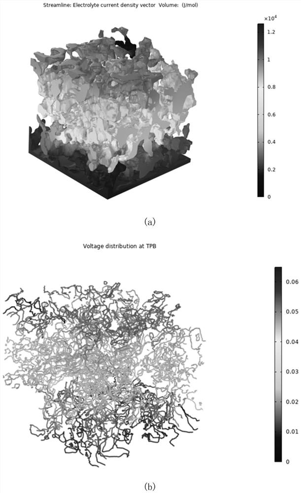
The invention provides a method for establishing a SOFC / SOEC electrode microstructure electrochemical model. The method comprises the following steps: identifying a three-phase boundary line at the intersection of yttrium oxide-stabilized zirconium oxide, nickel and a gaseous phase in an anode microstructure grid unit; establishing a coupling relationship among gas, ion and electron diffusion equations; applying a constant ion and electron flux boundary condition to the boundary of a current collector and an electrolyte, applying a constant gas concentration boundary condition near the current collector, and finally, using a separated solver to carry out steady-state solving to obtain the electrochemical characteristics of the microelectrode. By adopting the technical scheme, the electrochemical model with fully coupled gas, ion and electron diffusion equations is established, and a series of simulation results such as electrochemical potential distribution, ion current and electron current distribution, gas concentration distribution condition and relation between overpotential and input current density in the YSZ can be obtained according to the calculation result of the model; and the invention has certain guiding significance on electrode structure optimization and engineering design.

Description

technical field [0001] The invention belongs to the technical field of solid oxide fuel cells, in particular to a method for establishing an electrochemical model of the microstructure of SOFC / SOEC electrodes. Background technique [0002] Solid oxide fuel cell (SOFC) / solid oxide electrolysis cell (SOEC) has received increasing attention as a promising energy conversion device for efficient utilization of renewable energy. , the traditional SOFC / SOEC operates at a relatively high temperature of 600--1000°C to ensure rapid diffusion of oxygen ions in the electrolyte. In order to optimize the operating characteristics of SOFC / SOEC at different operating temperatures and operating states, it is very important to understand the reaction kinetics of SOFC / SOEC electrodes. [0003] The anode / cathode of industrial SOFC / SOEC is mainly composed of submicron-sized nickel (electronic conductor and catalyst) and 8YSZ (ionic conductor: 8mol% Y2O3 doped zirconia) particles, and the fuel g...

Claims


Application Information

Patent Timeline
IPC IPC(8): G06F30/23G06F111/10
CPCG06F30/23G06F2111/10Y02E60/50
Inventor 焦震钧苏云鹏
Owner HARBIN INST OF TECH SHENZHEN GRADUATE SCHOOL
Learn More