
A Speed ​​Control System of Switched Reluctance Motor with Power Factor Correction

A switched reluctance motor, power factor correction technology, applied in control systems, motor control, vector control systems, etc., can solve problems such as reducing power factor and power quality, reducing energy conversion efficiency, and unsatisfactory power quality. Power factor and power quality, the effect of simplifying control schemes, reducing control complexity

Active Publication Date: 2022-06-21
JIANGSU UNIV
View PDF1 Cites 0 Cited by
  • Summary
  • Abstract
  • Description
  • Claims
  • Application Information

AI Technical Summary

Problems solved by technology

Since the switched reluctance motor and other vehicle loads require DC input, the AC power generated by the generator and the AC grid needs to be rectified by a rectifier. However, the traditional diode rectifier often reduces the power factor and power quality, which is Reduce energy conversion efficiency, and even bring potential threats to electrical equipment
To solve this problem, the traditional method is to add a power factor correction front-end circuit to improve the power factor. However, in this method, the current total harmonic distortion and power quality are still not ideal, and the control complexity of the system is increased.

Method used


Image

  • A Speed ​​Control System of Switched Reluctance Motor with Power Factor Correction
  • A Speed ​​Control System of Switched Reluctance Motor with Power Factor Correction
  • A Speed ​​Control System of Switched Reluctance Motor with Power Factor Correction

Examples


Embodiment Construction

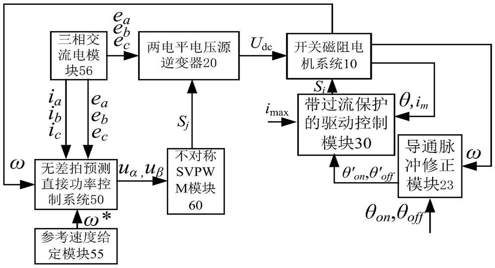
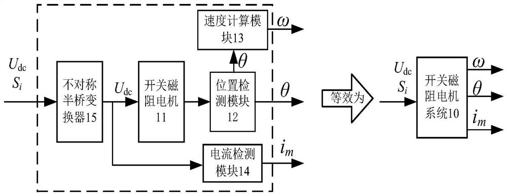
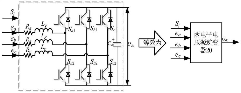
[0020] like figure 1 shown and figure 2 As shown, the present invention consists of a three-phase alternating current module 56, a two-level voltage source inverter 20, an on-pulse correction module 23, a drive control module 30 with overcurrent protection, a deadbeat predictive direct power control system 50, reference The speed setting module 55 and the asymmetric SVPWM module 60 are composed, and are connected to the switched reluctance motor system 10 including the switched reluctance motor 11 to control the switched reluctance motor 11 in the switched reluctance motor system 10 . The three-phase AC power module 56 is connected to an external power supply and outputs a three-phase AC voltage e a ,e b ,e c and current i a ,i b ,i c , the output terminals of the three-phase AC power module 56 are respectively connected to the two-level voltage source inverter 20 and the deadbeat predictive direct power control system 50, and the three-phase AC voltage e a ,e b ,e c...


PUM


Abstract

The invention discloses a switched reluctance motor speed control system with power factor correction, which comprises a three-phase alternating current module, a two-level voltage source inverter, a conduction pulse correction module, a drive control module with overcurrent It is composed of beat prediction direct power control system, reference speed given module and asymmetrical SVPWM module. In consideration of motor performance and interference to external speed control, a conduction pulse correction module that can correct conduction pulse is adopted, combined with Drive control module for over-current protection, improve power factor and power quality, synthesize desired voltage vector through asymmetric SVPWM method, reduce switching frequency, and achieve the goal by connecting a two-level voltage source inverter in series with an asymmetrical half-bridge converter Reduce the control complexity of the system while utilizing deadbeat predictive direct power control to achieve a stable and enhanced DC bus voltage, ensuring fast speed regulation by bidirectionally manipulating the energy flow in the two-level voltage source inverter.

Description

technical field [0001] The invention belongs to the technical field of motor control applications, and in particular relates to a switched reluctance motor speed control system for adjusting the speed of the switched reluctance motor. Background technique [0002] At present, most of the motors used in vehicles are induction motors and permanent magnet motors. For induction motors, their speed regulation performance is poor, and it is difficult to perform precise control, and the requirements for the control system of the motor are relatively high. For permanent magnet motors, due to the existence of permanent magnet materials, so The stability under high temperature and high magnetic field environment is difficult to guarantee. Switched reluctance motors quickly become automotive motors due to their advantages of not requiring rare earth permanent magnets, low cost, high reliability and outputting DC voltage. Since switched reluctance motors and other vehicle loads require...

Claims


Application Information

Patent Timeline
Patent Type & Authority Patents(China)
IPC IPC(8): H02P21/12H02P21/00H02P25/08H02P27/08H02P27/12
CPCH02P21/12H02P21/0003H02P25/0805H02P27/085H02P27/12H02P2207/05
Inventor 孙晓东金志佳邬江陵陈龙田翔周卫琪
Owner JIANGSU UNIV
Learn More