Evaporation-induced battery based on carbon material surface function modification

A technology of evaporation induction and carbon materials, applied in the direction of electrical components, etc., can solve problems such as energy loss, and achieve the effects of improving electricity production efficiency, simple and easy-to-obtain raw materials, and simple preparation processes

Pending Publication Date: 2021-09-24
TIANJIN UNIV
View PDF0 Cites 0 Cited by
  • Summary
  • Abstract
  • Description
  • Claims
  • Application Information

AI Technical Summary

Problems solved by technology

The technology of using environmental energy conversion in many cleaning processes is considered to be a new type of energy with great development prospects, such as solar cells, thermoelectric cells, piezoelectric nano-batteries and tribo-nano-liquids, etc. However, the generation of these electric energies often requires external energy. Stimuli like sunlight, thermal gradients, pressure gradients, etc., which tend to cause energy loss

Method used


Image

  • Evaporation-induced battery based on carbon material surface function modification
  • Evaporation-induced battery based on carbon material surface function modification

Examples


Embodiment 1

[0029] The preparation of embodiment 1 MOF801, concrete steps are as follows:

[0030] (1) 2.03g (17.5mmol) fumaric acid and 5.6g (17.5mmol) ZrOCl 2 ·8H 2 O was dissolved in a mixed solvent of DMF and formic acid (70 L and 24.5 mL, respectively). Then the mixture was placed in a polytetrafluoroethylene-lined autoclave and heated at 130°C for 6h.

[0031] (2) The product was collected through a microporous membrane (45 μm pore size) vacuum filtration device, washed three times with 60 mL of DMF, three times with 40 mL of methanol, and dried in air.

[0032] (3) The above MOF samples were placed in a 15kPa vacuum oven and dried at 150°C for 24h.

Embodiment 2

[0033] Example 2 PEI-KB-FP electricity production voltage and PEI concentration experiment, the specific steps are as follows:

[0034] First prepare PEI aqueous solutions with concentrations of 0.4wt%, 0.2wt%, 0.1wt%, 0.05wt%, 0.025wt%, after ultrasonication for 30min, place the CB-SDBS-treated qualitative filter papers in the above solution respectively, and hydrothermally treat them at 70°C Take it out after 2 hours, and then dry it in a blast oven at 80°C for 30 minutes. Put the dried different PEI-modified PEI-KB-FP in a beaker filled with 0.5mol / L NaCl aqueous solution, where the wet end of PEI-KB-FP was connected to the reference electrode of the electrochemical workstation, and the dry end of PEI-KB-FP was Connect the terminal to the working electrode of the electrochemical workstation, and then adjust the specific parameters of the electrochemical workstation, measure and record the electricity production voltage value of PEI-KB-FP at 1000s, we found that PEI-KB-FP tr...

Embodiment 3

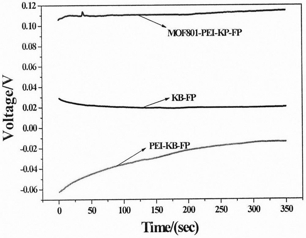
[0035] Example 3 Voltage comparison experiment of KB-FP, PEI-KB-FP, MOF801-PEI-KB-FP, the specific steps are as follows:

[0036] First prepare KB-FP, PEI-KB-FP, MOF801-PEI-KB-FP power generation modules, and connect the stems of KB-FP, PEI-KB-FP, and MOF801-PEI-KB-FP with a multi-channel electrochemical workstation terminal and wet terminal, the connection method is the same as in Example 2, three different power generation modules are immersed in 0.6mol / L NaCl aqueous solution at the same time, and the multi-channel workstation is used to record the power production of the battery, and record KB-FP, PEI -KB-FP, MOF801-PEI-KB-FP's power generation voltage value at 1000s, figure 2 The voltage comparison of KB-FP, PEI-KB-FP, MOF801-PEI-KB-FP is shown.


PUM


Abstract

The invention discloses an evaporation-induced battery based on carbon material surface functional modification. Counterions entering a pore channel are changed by modifying the Zeta potential of a qualitative filter paper capillary channel, and then output voltage and current are changed. According to the invention, the MOF material with high Zeta potential and the PEI are used for modifying the surface potential of the carbon material for the first time to form the novel evaporation-induced battery with the surface function modified by the carbon material, so that a new research thought is provided for modification of the evaporation-induced power generation battery in the future.

Description

technical field [0001] The invention relates to an evaporation induction battery based on carbon material surface functional modification. Background technique [0002] The energy problem has become one of the three major problems in the world today. Problems such as environmental pollution and resource shortage caused by the use of fossil energy have attracted more and more attention. At present, the demand for energy in human society is not only the increase in quantity, but also higher requirements for the diversification of energy. Therefore, more and more clean energy has been discovered to meet people's new requirements for energy. The technology of using environmental energy conversion in many cleaning processes is considered to be a new type of energy with great development prospects, such as solar cells, thermoelectric cells, piezoelectric nano-batteries and tribo-nano-liquids, etc. However, the generation of these electric energies often requires external energy. ...

Claims


Application Information

Patent Timeline
Patent Type & Authority Applications(China)
IPC IPC(8): H01M14/00
CPCH01M14/00
Inventor 刘宪华李璟玉李赟雪
Owner TIANJIN UNIV
Why Eureka
Try Eureka