Friction welding material adding equipment and method

A friction welding and equipment technology, applied in the field of additive manufacturing, can solve the problems of friction heat generation between the piston and the rod body, poor fusion, and reduce the overall performance, so as to improve the utilization rate of materials, reduce the extrusion force, and improve the production efficiency. Effect

Active Publication Date: 2021-10-15
长沙弗瑞克科技有限公司
View PDF7 Cites 5 Cited by
  • Summary
  • Abstract
  • Description
  • Claims
  • Application Information

AI Technical Summary

Problems solved by technology

However, in the high-energy beam additive manufacturing process, the high temperature will cause the material to melt. Due to the fast forming speed, there will inevitably be defects such as pores, cracks, and poor fusion when the material is solidified, and the subsequent processing and manufacturing will be harmful to the solidified material. Thermal action may reduce the overall performance, which has a more serious impact on the widely used low-melting point light metal materials such as aluminum and magnesium alloys. As a solid-phase additive manufacturing method, friction additive manufacturing has a grain It is a kind of additive method with development potential, and has unique advantages in light alloy additive.
[0004] Invention patent CN202110134068.9 discloses a friction stir additive device and additive manufacturing method. In this method, the wire is fed into the hollow cavity of the stirring head, and the piston is used to squeeze the wire into a rod and then rotate with the stirring head. , friction with the substrate to be added to achieve material addition, but this method has two shortcomings. One is that the wire is very tightly attached to the stirring head after being squeezed in the hollow cavity of the stirring head, and it is difficult to squeeze the additive material when it is working. The other one is that when the stirring head rotates with the rod, it rotates relative to the piston, which causes the friction between the piston and the rod to generate heat. After the rod softens, the piston will be inserted into the rod, which will lead to more material It is difficult to extrude, and the piston and the rod will be welded together after the rotation is stopped, which will affect the operation of the equipment
[0005] Invention patent CN201810234931.6 discloses a flow friction additive manufacturing device and additive manufacturing method. The method is thermally plasticized by the friction generated by the relative rotation between the rod and the shaft shoulder inner cavity, and the thermally plasticized material is Under the action of upsetting force, it flows out along the central through hole at the lower end of the shaft shoulder, and the outflowing thermoplastic material diffuses and deposits on the substrate to be added under the action of relative rotation between the outer end surface of the shaft shoulder and the surface of the substrate to be added. On the surface of the additive area, the disadvantage of this method is that in order to achieve the relative rotational friction between the rod and the inner cavity of the shoulder, the cross-sectional size of the rod will always be larger than the central through hole at the lower end of the shoulder, so the additive material cannot be fully extruded , the softened material accumulates in the cavity, which affects the extrusion and production efficiency of the material

Method used


Image

  • Friction welding material adding equipment and method
  • Friction welding material adding equipment and method
  • Friction welding material adding equipment and method

Examples


Embodiment 1

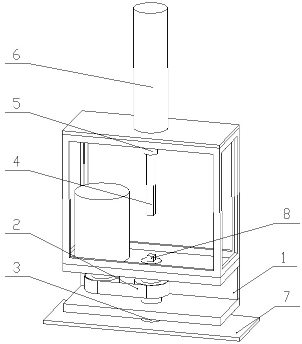
[0049] Such as Figure 1~Figure 4 As shown, a friction welding additive equipment includes a machine base 1, a rotating device 2, a shaft shoulder 3, an extrusion rod 4, a shaft sleeve 5, and an extrusion device 6.

[0050] The rotating device 2 is installed on the machine base 1 and includes a motor and a pulley drive. The motor drives the pulley to drive the shaft shoulder 3 to rotate, and the rotation speed of the shaft shoulder 3 is adjustable from 100 to 2000 r / min.

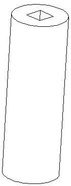
[0051] The shaft shoulder 3 has a through hollow inner cavity, and the section of the hollow inner cavity is a through square.

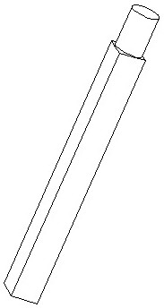
[0052] The extrusion rod 4 moves in the hollow cavity of the shaft shoulder 3, and the section shape of the part of the extrusion rod 4 inserted into the hollow cavity of the shaft shoulder 3 is square, and the extrusion rod 4 cooperates with the square hollow cavity of the shaft shoulder 3, The shaft shoulder 3 can rotate with the extrusion rod 4 when it rotates.

[0053] The sh...

Embodiment 2

[0058] The specific implementation process includes the following implementation steps:

[0059] S1. Move the device down so that the shoulder 3 contacts the surface of the substrate 7 to be added;

[0060] S2, putting the base material 8 into the hollow inner cavity of the shoulder 3;

[0061] S3, the extrusion device 6 drives the bushing 5 to drive the extrusion rod 4 to move downward, and inserts it into the hollow inner cavity of the shaft shoulder 3;

[0062] S4. The rotating device 2 drives the shaft shoulder 3 to rotate, drives the base material 8 and the extrusion rod 4 to rotate synchronously, the base material 8 and the matrix 7, and the shaft shoulder 3 and the matrix 7 rub against each other to generate heat to soften the base material 8 and the matrix 7;

[0063] S5. The extrusion device 6 continues to drive the bushing 5 to drive the extrusion rod 4 to move downward to give the base material 8 downward extrusion force, extruding the softened base material and sp...

Embodiment 3

[0066] In the specific implementation process, it can also be realized through the following implementation steps:

[0067] S1. Move the friction welding additive equipment down so that the end face of the shaft shoulder is higher than the surface of the substrate to be additive by a certain height, and the height is 0.5mm~5mm;

[0068] S2, putting the base metal into the hollow cavity of the shaft shoulder;

[0069] S3. The drive shaft sleeve of the extrusion device drives the extrusion rod to move downward and insert it into the hollow inner cavity of the shaft shoulder;

[0070] S4. The rotating device drives the shaft shoulder to rotate, drives the base material and the extrusion rod to rotate synchronously, and the base material and the base body rub against each other to generate heat to soften the base material and the base body;

[0071] S5. The extrusion device continuously drives the shaft sleeve to drive the extrusion rod to move downward to give the base material ...


PUM


Abstract

The invention relates to friction welding material adding equipment. The friction welding material adding equipment comprises a machine base, a rotating device, a shaft shoulder, an extrusion rod, a shaft sleeve and an extrusion device. The invention further provides a method for carrying out material adding manufacturing by adopting the friction welding material adding equipment. According to the friction welding material adding equipment, high-quality material adding manufacturing of metal materials such as aluminum alloy can be achieved, and the material utilization rate and the production efficiency are improved.

Description

technical field [0001] The invention relates to the technical field of additive manufacturing, in particular to a friction welding additive equipment and method. Background technique [0002] Additive manufacturing technology is a brand-new manufacturing method that is different from traditional casting, forging, welding and other hot processing "equal material forming" technologies and cold processing "subtractive material forming" technologies such as turning, milling, and grinding. The method of manufacturing solid parts is a bottom-up manufacturing method compared to the traditional material removal-machining technology. [0003] At present, the commonly used metal additive manufacturing methods include laser, electron beam and electric arc additive manufacturing, which have the advantages of rapid prototyping and high processing precision, and are widely used in the fields of superalloy forming and precision component manufacturing. However, in the high-energy beam add...

Claims


Application Information

Patent Timeline
Patent Type & Authority Applications(China)
IPC IPC(8): B23K20/12B23K20/26B33Y10/00B33Y30/00
CPCB23K20/122B23K20/1245B23K20/1215B33Y10/00B33Y30/00
Inventor 喻坤周桢
Owner 长沙弗瑞克科技有限公司
Why Eureka
Try Eureka