
High-precision digital MEMS gyroscope control system and method

A control system and high-precision technology, applied in the field of MEMS sensors, can solve the problems of signal delay changes in signal processing links, affecting signal decomposition accuracy, feedback force output accuracy, lack of solutions, etc., to meet the requirements of high-precision modulation and demodulation, The effect of improving the performance index of the full temperature range and facilitating the realization of the circuit

Active Publication Date: 2021-10-22
BEIJING MXTRONICS CORP +1
View PDF10 Cites 5 Cited by
  • Summary
  • Abstract
  • Description
  • Claims
  • Application Information

AI Technical Summary

Problems solved by technology

[0003] At present, research on MEMS gyroscopes mainly focuses on quadrature error elimination methods, temperature characteristics and calibration, and system bandwidth. In the control system of the prior art, both modes also adopt closed-loop control methods to eliminate Error, to expand the dynamic range of the system and improve the system bandwidth. However, these systems pay little attention to the error caused by the inaccuracy of the modulation and demodulation signal itself during signal processing, and lack of solutions. The default modulation and demodulation signal and the detection output of the gyro sensitive structure Signals are fully in-phase and quadrature
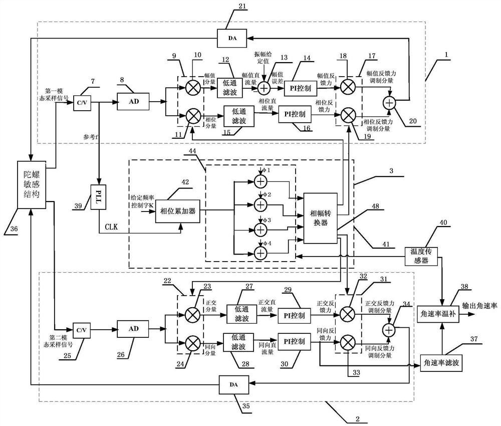
However, in the actual circuit, due to the incomplete symmetry of the processing of the gyro device, the characteristic difference between the drive and detection path links, the existence of the difference between the modulation and demodulation signal generation circuit and the detection and drive circuit link characteristics, and environmental disturbances, the demodulation signal It is difficult to achieve complete synchronization with the demodulated signal, the feedback driving signal and the output displacement signal of the sensitive structure, which will affect the signal decomposition accuracy and feedback force output accuracy, thus directly affecting the measurement accuracy of the gyroscope
[0004] At the same time, the gyro sensitive structure is highly sensitive to temperature, and the resonant frequency is easy to fluctuate with temperature. Moreover, the component characteristics of the processing circuit itself, especially the resistance, inductance and parasitic characteristics of the analog processing circuit part are particularly sensitive to temperature, resulting in temperature changes. Causes signal delay changes on the signal processing link, which will directly cause the modulation and demodulation signal to be unable to be given as expected and seriously deteriorate the full temperature characteristics of the gyroscope
In the control system of the prior art, the temperature sensor is integrated in the processing circuit to compensate the angular rate zero bias and the scale factor. However, because there are many reasons for the poor temperature characteristics, the relationship between the angular rate and the temperature is usually very complicated. , the polynomial fitted with a limited number of times and the method of multi-stage compensation are difficult to achieve satisfactory results, so simply performing temperature compensation on the output angular rate can no longer meet the requirements

Method used


Image

  • High-precision digital MEMS gyroscope control system and method
  • High-precision digital MEMS gyroscope control system and method

Examples


Embodiment Construction

[0026] In order to make the object, technical solution and advantages of the present invention clearer, the implementation manner of the present invention will be further described in detail below in conjunction with the accompanying drawings.

[0027] MEMS gyro is an inertial device, and its working principle is the principle of Coriolis force, which can be compared to two mutually orthogonal damping-spring systems. When the mass block vibrates in simple harmonic along the driving direction, if there is an angular velocity change in the direction perpendicular to the driving-detecting plane, a Coriolis force proportional to the angular velocity will be induced in the detecting direction. The expression of Coriolis force Fc is:

[0028] Fc=2m*v*Ω (1)

[0029] Among them, m is the mass of the gyro sensitive structure, v is the effective vibration velocity of the driving mode, and Ω is the applied angular rate.

[0030] In the gyroscope control system, keep the vibration ampli...


PUM


Abstract

A high-precision digital MEMS gyroscope control system comprises a driving mode closed-loop control loop, a detection mode closed-loop control loop and a modulation-demodulation signal phase closed-loop control loop, so that the system can always change along with the resonant frequency of a gyroscope. Herein, the phases of the two-mode modulation-demodulation signals are respectively adjusted through a driving mode demodulation signal phase adjustment value phi 1, a driving mode modulation signal phase adjustment value phi 2, a detection mode demodulation signal phase adjustment value phi 3 and a detection mode modulation signal phase adjustment value phi 4 which are subjected to temperature compensation. Through the system, the influence of modulation and demodulation signal phase errors on the gyroscope detection precision in the current gyroscope control system is solved, and the performance index of the MEMS gyroscope is greatly improved.

Description

technical field [0001] The invention relates to a high-precision digital MEMS gyro control system and method, in particular to an optimized high-precision MEMS gyro control system for detecting the angular velocity of an object, belonging to the technical field of MEMS (Micro-Electro Mechanical System) sensors. Background technique [0002] Compared with traditional gyroscopes, MEMS gyroscopes have the advantages of low power consumption, small size, low cost, and light weight, and are widely used in the aerospace industry, automotive electronics, and consumer electronics. However, in high-precision application systems, due to the limited accuracy of MEMS sensors, gyroscopes such as optical fibers and lasers are currently used more. With the continuous improvement of the MEMS processing level, many research institutes and universities have developed high-performance MEMS gyro sensitive structures, which need to be equipped with high-precision control systems to optimize the ...

Claims


Application Information

Patent Timeline
Patent Type & Authority Applications(China)
IPC IPC(8): G01C19/5776B81B7/02
CPCG01C19/5776B81B7/02
Inventor 熊开利张龙张奇荣权海洋朱红叶泽刚王浩康苗苗
Owner BEIJING MXTRONICS CORP
Learn More