
Frequency selection microstrip splitter

A technology of frequency selection and splitter, applied in circuits, waveguide devices, advanced technology, etc., can solve the problems of increasing circuit design complexity, increasing power consumption and cost, reducing reliability, etc., to reduce complexity and Difficult to debug, easy to debug, easy to achieve

Active Publication Date: 2021-10-22
10TH RES INST OF CETC
View PDF13 Cites 0 Cited by
  • Summary
  • Abstract
  • Description
  • Claims
  • Application Information

AI Technical Summary

Problems solved by technology

But this design has the following problems: (1) Since the power distribution circuit distributes a certain output power to each branch circuit in a certain proportion, the energy loss is large
Such a design method not only increases the complexity of circuit design, reduces reliability, but also increases power consumption and cost, and requires corresponding debugging time, which causes a lot of inconvenience to relevant practitioners

Method used


Image

  • Frequency selection microstrip splitter
  • Frequency selection microstrip splitter
  • Frequency selection microstrip splitter

Examples


Embodiment Construction

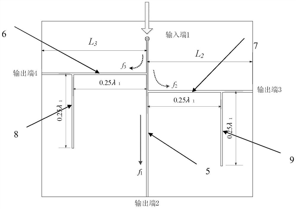
[0017] refer to figure 1 . In the preferred embodiment described below, a frequency selective microstrip splitter includes: a main channel microstrip line 5 etched on a microstrip printed board, passing through the main channel input port 1 to the main channel output port 2 , are respectively vertically connected to the first branch microstrip line 6 reaching the first branch output port 4 on the main road microstrip line 5, located below the first branch microstrip line 6 and reversely and vertically connected to the main road microstrip line 5 The second branch microstrip line 7 reaching the second branch output port 3 . Among them: under the first branch microstrip line 6 and the second branch microstrip line 7, respectively connected to the main road microstrip line 5 mirror symmetrical parallel, one end suspended, the length is 0.25λ 1 The first impedance transformation line 8 and the second impedance transformation line 9, thereby constitute the equivalent circuit of t...


PUM


Abstract

A frequency selection microstrip splitter disclosed by the invention is high in isolation degree, small in signal energy loss and easy to debug. According to the technical scheme, a first impedance conversion line and a second impedance conversion line are connected below a first branch microstrip line and a second branch microstrip line respectively, one ends of the first impedance conversion line and the second impedance conversion line are suspended, and the length of the first impedance conversion line and the length of the second impedance conversion line are 0.25 lambda 1, so that an equivalent circuit of the frequency selection microstrip splitter is formed; n paths of radio frequency transmission frequency signals fn of which the corresponding medium wavelengths lambda are lambda n respectively enter a main path microstrip line from an input port, and then sequentially reach a main path output port, a first branch output port and a second branch output port; a set radio frequency signal is output to a terminal load device R1 through the equivalent circuit main path output port, a modulated control signal is output to a terminal device load R2 through the first branch output port, and a direct current signal is output to a terminal load device R3 through the second branch input port.

Description

technical field [0001] The invention relates to the technical field of microwave circuits, in particular to a frequency-selective microstrip splitter used in broadband co-cable transmission technology for internal equipment of satellite communication systems or satellite navigation systems. Background technique [0002] The satellite communication system and the satellite navigation system are mainly composed of two parts: an active antenna and a transceiver terminal. The two parts are connected by using various types of radio frequency, digital, power supply cables, etc., but limited by the space and size of the platform, there are transmission The distance is short, the amount of wiring is large, the construction is complicated, and the maintenance is inconvenient. In the comparison of various transmission technology methods, broadband co-cable transmission technology can not only solve the above problems, but also ensure the quality of signal transmission, reduce engineer...

Claims


Application Information

Patent Timeline
Patent Type & Authority Applications(China)
IPC IPC(8): H01P1/213
CPCH01P1/213Y02D30/70
Inventor 胡大成何斌熊文毅何凌云杜明胡云何宣霖
Owner 10TH RES INST OF CETC
Learn More