Flue gas desulfurization and denitrification adsorption device for sintering machine
A technology of desulfurization, denitrification, and adsorption devices, which is applied in gas treatment, membrane technology, and dispersed particle separation, etc., can solve the problems of difficulty in prolonging the contact time between activated carbon and delayed contact time, short contact time between activated carbon and flue gas, and small contact area, and achieves high efficiency. The effect of flowability and adsorption capacity, reduction of consumption and operating costs, increase of contact area
- Summary
- Abstract
- Description
- Claims
- Application Information
AI Technical Summary
Problems solved by technology
Method used
Image

Examples
Embodiment Construction
[0016] The present invention will be described in detail below in conjunction with the embodiments and the accompanying drawings. The protection scope of the present invention is not limited to the embodiments, and any changes made by those skilled in the art within the scope defined in the claims also belong to the protection scope of the present invention.
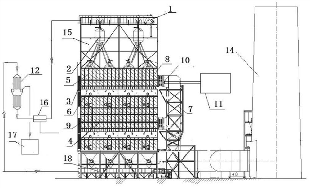
[0017] The sintering machine flue gas desulfurization and denitrification adsorption device of the present invention, such as figure 1 As shown, the device includes a chain bucket machine 1, a material tank 2, an adsorption tower 3, an ammonia gas supply unit 11 and an activated carbon desorption tower 12, and the chain bucket machine is connected in series with the activated carbon desorption tower through the top and bottom of the adsorption tower 3. The adsorption tower is composed of 4 desulfurization and denitrification units 15, forming a matrix structure in the adsorption tower. The upper part of the chain bucket...
PUM
 Abstract
Description
Claims
Application Information
 - Generate Ideas
- Intellectual Property
- Life Sciences
- Materials
- Tech Scout
- Unparalleled Data Quality
- Higher Quality Content
- 60% Fewer Hallucinations
Browse by: Latest US Patents, China's latest patents, Technical Efficacy Thesaurus, Application Domain, Technology Topic, Popular Technical Reports.
© 2025 PatSnap. All rights reserved.Legal|Privacy policy|Modern Slavery Act Transparency Statement|Sitemap|About US| Contact US: help@patsnap.com