
EUV mask plate alignment mark and optimization method and preparation method thereof

A technology for aligning marks and masks, which is applied in the field of lithography, can solve the problems of defect positioning accuracy, poor detection accuracy and repeatability of quasi-mark positions, and poor imaging contrast, so as to improve the intensity of scattering signals, improve measurement repeatability, The effect of small processing error

Pending Publication Date: 2021-10-29
CHANGCHUN INST OF OPTICS FINE MECHANICS & PHYSICS CHINESE ACAD OF SCI
View PDF0 Cites 2 Cited by
  • Summary
  • Abstract
  • Description
  • Claims
  • Application Information

AI Technical Summary

Problems solved by technology

[0006] An object of the present invention is to provide an EUV mask alignment mark and its optimization method and preparation method, which can improve the accuracy of defect positioning, and are used to solve the poor imaging contrast of the existing alignment mark position and the alignment mark position. Problems with poor detection accuracy and repeatability

Method used


Image

  • EUV mask plate alignment mark and optimization method and preparation method thereof
  • EUV mask plate alignment mark and optimization method and preparation method thereof
  • EUV mask plate alignment mark and optimization method and preparation method thereof

Examples


Embodiment Construction

[0035] The following description serves to disclose the invention to enable those skilled in the art to practice the invention. The preferred embodiments described below are given by way of example only, and other obvious modifications will occur to those skilled in the art. The basic principles of the invention defined in the following description may be applied to other embodiments, variations, modifications, equivalents, and other technical solutions without departing from the spirit and scope of the invention.

[0036]It should be understood by those skilled in the art that in the disclosure of the present invention, the terms "vertical", "horizontal", "upper", "lower", "front", "rear", "left", "right", The orientations or positional relationships indicated by "vertical", "horizontal", "top", "bottom", "inside", "outside", etc. are based on the orientations or positional relationships shown in the accompanying drawings, which are only for the convenience of describing the ...


PUM

PropertyMeasurementUnit
widthaaaaaaaaaa
heightaaaaaaaaaa
angleaaaaaaaaaa

Abstract

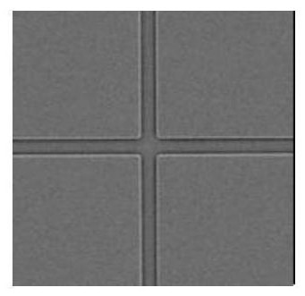
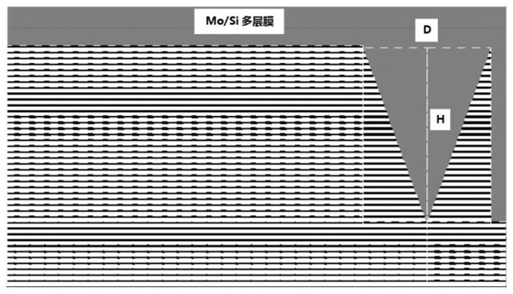
The invention relates to an EUV mask plate alignment mark and a design method and a preparation method thereof. The edge of an EUV mask plate is of a V-shaped groove structure, so that the scattering signal intensity of the edge of the alignment mark can be remarkably improved, and meanwhile, the imaging light spot mass center detection precision at the edge position of the alignment mark is improved, and accordingly the detection precision and repeatability of the alignment mark position can be effectively improved, the defect positioning precision is further improved, the subsequent compensation and processing of the EUV mask plate defects are facilitated, and the production capacity is improved.

Description

technical field [0001] The invention relates to the technical field of photolithography, in particular to an EUV mask alignment mark and an optimization method and a preparation method thereof. Background technique [0002] The progress of the semiconductor industry has benefited from the development of very large-scale integrated circuits. Lithography is the core technology for manufacturing chips. In the entire chip manufacturing process, the implementation of almost every process is inseparable from the technology of lithography. It is precisely through the continuous development of lithography technology to reduce the processing line width of semiconductor devices, so as to achieve high integration, high performance and low power consumption of integrated circuits. Projection exposure lithography is an exposure process that uses the principle of optical projection imaging to transfer the pattern on the mask to the wafer coated with photoresist. The fastest and most viab...

Claims


Application Information

Patent Timeline
Patent Type & Authority Applications(China)
IPC IPC(8): H01L21/027H01L21/033H01L23/544
CPCH01L21/0337H01L21/0338H01L21/0274H01L23/544H01L2223/54426
Inventor 邓文渊喻波姚舜
Owner CHANGCHUN INST OF OPTICS FINE MECHANICS & PHYSICS CHINESE ACAD OF SCI
Learn More