Automatic processing technology for high-fiber bread
A processing technology and high-fiber technology, which is applied in the field of high-fiber bread automatic processing technology, can solve the problems of material waste and so on, and achieve the effect of increasing output, reducing production cost and increasing income
- Summary
- Abstract
- Description
- Claims
- Application Information
AI Technical Summary
Problems solved by technology
Method used
Image
Examples
Embodiment 1
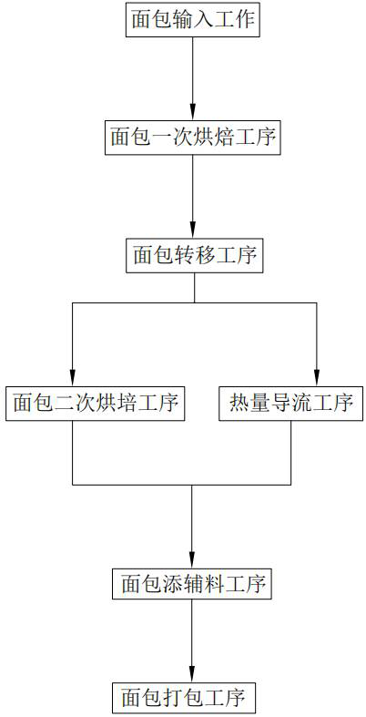
[0108] Such as figure 1 Shown, a kind of high-fiber bread automatic processing technique comprises:
[0109] Step 1, the bread input process, put several groups of bread into the storage space a246 of the corresponding bearing assembly 24 in sequence, and then start the driving motor 235 of the first driving assembly 23, and the driving motor 235 drives the first transmission member 232 to drive, The transmission first transmission member 232 then drives the transmission rack 231 to move horizontally and laterally until the moving assembly 22 enters the oven 1;
[0110] Step 2, a bread baking process, after the mobile component 22 completely enters the baking oven 1, an electrical signal sends out an instruction, the doors of the entrance 11 and the exit 12 are automatically closed, the baking oven 1 is opened, and the bread is placed in the storage space a246 for primary baking. Baking work;
[0111] Step 3, the bread transfer process, after the surface of the bread has a c...
Embodiment 2
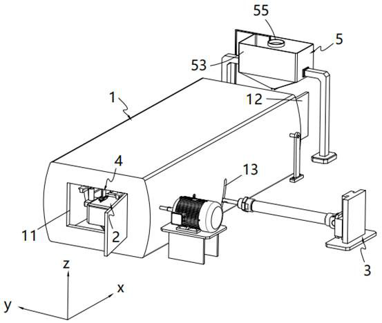
[0127] Such as figure 2 Shown, a kind of high-fiber bread automatic processing device comprises:
[0128] Oven 1;
[0129] The oven 1 is provided with an inlet 11 and an outlet 12 along its length direction, and the side wall of the oven 1 is provided with a first waist groove 13, and the inlet 11 and the outlet 12 are driven by electrical signals;
[0130] Transmission mechanism 2;
[0131] The transmission mechanism 2 includes two sets of support rails 21 installed along the length direction of the oven 1 and installed on the upper end of the oven 1, a moving assembly 22 slidingly arranged under the support rails 21, for A first drive assembly 23 that drives the moving assembly 22 to reciprocate, and a bearing assembly 24 mounted on the moving assembly 22 and arranged along the length direction of the oven 1;
[0132] Shaking mechanism 3;
[0133] The shaker mechanism 3 includes a support shaft 31 installed on the upper end of the oven 1 and located in the middle of the...
Embodiment 3
[0189] Such as figure 2 , Figure 11 to Figure 12 As shown, the parts that are the same as or corresponding to those in the second embodiment are marked with the corresponding reference numerals in the second embodiment. For the sake of simplicity, only the differences from the second embodiment will be described below. The difference between this embodiment three and embodiment two is:
[0190] further, such as figure 2 , Figure 11 to Figure 12 Shown, described supplementary material mechanism 5 comprises:
[0191] Interlocking rack 51;
[0192] The interlocking rack 51 is installed on the sliding frame 221 and is configured as an intermittent tooth structure, and the interlocking rack 51 is configured as a one-way tooth structure;
[0193] Linkage wheel 52;
[0194] The interlocking wheel 52 is engaged with the interlocking rack 51 and installed on the wheel frame;
[0195] Installation warehouse 53;
[0196] The installation bin 53 is located on one side of the i...
PUM
 Abstract
Description
Claims
Application Information
 - R&D
- Intellectual Property
- Life Sciences
- Materials
- Tech Scout
- Unparalleled Data Quality
- Higher Quality Content
- 60% Fewer Hallucinations
Browse by: Latest US Patents, China's latest patents, Technical Efficacy Thesaurus, Application Domain, Technology Topic, Popular Technical Reports.
© 2025 PatSnap. All rights reserved.Legal|Privacy policy|Modern Slavery Act Transparency Statement|Sitemap|About US| Contact US: help@patsnap.com


