Laser cladding method for wear-resistant alloy of inner bore

A laser cladding, wear-resistant alloy technology, applied in the direction of metal material coating process, coating, etc., can solve the problems of difficult quality performance, complex realization process, low processing efficiency, etc., achieve small heat affected zone, low dilution rate , the effect of high stability

Pending Publication Date: 2021-11-02
R&D TECH SUZHOU
View PDF4 Cites 0 Cited by
  • Summary
  • Abstract
  • Description
  • Claims
  • Application Information

AI Technical Summary

Problems solved by technology

[0003] The conventional inner wall cladding process has a wide range of options, such as GMAW, FACW, SMAW, SAW, GTAW and other surfacing welding processes can meet the requirements. ), limited by the size of the inner cavity and the type of welding material, the equipment of these welding methods cannot reach the inner cavity for surfacing cladding. Such as the wear-resistant cladding of Stellite1#6# alloy, this type of alloy welding material has high hardness and can To reach ≥38,48HRC, the type of welding material is generally cast into rods, so manual arc welding electrodes and argon arc welding (SMAW, GTAW) are used, and the inner diameter that can be cladding is required to be at least 300mmX300mmX300mm, and this is done manually Cladding surfacing welding of similar materials has low processing efficiency, it is difficult to achieve stable quality performance, and welding defects are extremely prone to occur. The workpiece needs to be preheated to 250°C before surfacing welding, and the working environment of the welder is harsh.
[0004] At present, laser cladding technology can only clad large-diameter pipes, but for medium- and small-diameter pipes, it is mainly because the cladding is limited by the space, it is difficult for the laser head to enter the pipe, the implementation process is complicated and expensive, and the conventional The laser of the laser cladding processing head starts to focus at a relatively far position, the processing efficiency is low and the protective mirror is easily damaged, making it difficult to achieve good processing quality

Method used


Image

  • Laser cladding method for wear-resistant alloy of inner bore
  • Laser cladding method for wear-resistant alloy of inner bore

Examples


Embodiment Construction

[0026] The technical solution of this patent will be further described in detail below in conjunction with specific embodiments.

[0027] Embodiments of the present patent are described in detail below, examples of which are shown in the drawings, wherein the same or similar reference numerals designate the same or similar elements or elements having the same or similar functions throughout. The embodiments described below by referring to the figures are exemplary and are only used for explaining the patent, and should not be construed as limiting the patent.

[0028] In the description of this patent, it is to be understood that the terms "center", "upper", "lower", "front", "rear", "left", "right", "vertical", "horizontal", The orientation or positional relationship indicated by "top", "bottom", "inner", "outer", etc. is based on the orientation or positional relationship shown in the drawings, and is only for the convenience of describing this patent and simplifying the des...


PUM

PropertyMeasurementUnit
thicknessaaaaaaaaaa

Abstract

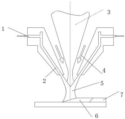
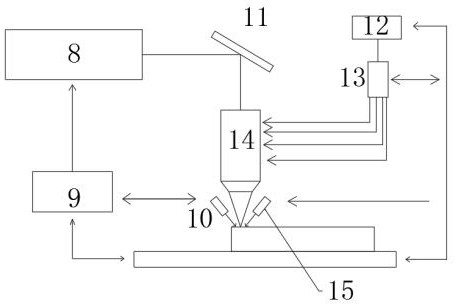
The invention belongs to the technical field of deep sea oil extraction machinery, and particularly provides a laser cladding method for wear-resistant alloy of an inner bore. According to the scheme, the laser cladding method involves an inner bore laser cladding gun, a laser, a powder feeder and a molten pool, wherein a coaxial powder feeding cladding head is arranged at the output end of the inner bore laser cladding gun, and the molten pool is located under the coaxial powder feeding cladding head; and the output end of the powder feeder is connected with a four-flow powder distributor. The laser cladding method comprises the steps of S1, cleaning and S2, placing and preheating. In the step S1, the surface of a workpiece is wiped with acetone or alcohol; and in the step S2, the workpiece is placed under the inner bore laser cladding gun, the coaxial powder feeding cladding head is right opposite to the inner bore, and the workpiece is preheated to 100-150 DEG C. According to the laser cladding method, the inner bore laser cladding gun head which is specially modified is adopted, cladding surfacing can be conducted on the inner wall of the workpiece with the small and medium aperture, powder is subjected to surfacing of the inner bore in a laser cladding manner by adopting a welding material type of powder alloy, and good metallurgical bonding is formed between a cladding layer and a base body.

Description

technical field [0001] The invention relates to the technical field of deep-sea oil extraction machinery, in particular to a wear-resistant alloy laser cladding method for an inner hole. Background technique [0002] In the fields of mining and deep-sea petroleum machinery, it is usually applied to many pipelines or anti-wear sleeves. In view of the harsh high-sulfur, high-sediment, and high-velocity conditions, the inner wall / cavity of these products will be affected by different degrees of erosion and wear during use. Its performance and service life, so how to increase the wear resistance and corrosion resistance of the inner wall of the pipeline is the key to solving this problem. [0003] The conventional inner wall cladding process has a wide range of options, such as GMAW, FACW, SMAW, SAW, GTAW and other surfacing welding processes can meet the requirements. ), limited by the size of the inner cavity and the type of welding material, the equipment of these welding me...

Claims


Application Information

Patent Timeline
Patent Type & Authority Applications(China)
IPC IPC(8): C23C24/10
CPCC23C24/103
Inventor 侯俊明
Owner R&D TECH SUZHOU
Why Eureka
Try Eureka