
Cutting machine

A cutting machine and frame technology, applied in the field of machinery, can solve the problems of frequent damage to the cutter, formation of some iron filings, and broken blades, etc., so as to improve cutting efficiency, avoid the time occupied by the position, and reduce the probability of damage.

Active Publication Date: 2021-11-05
扎赉诺尔煤业有限责任公司
View PDF11 Cites 1 Cited by
  • Summary
  • Abstract
  • Description
  • Claims
  • Application Information

AI Technical Summary

Problems solved by technology

The defects in the prior art are: the cutting knife is frequently damaged; since the steel pipe used for processing and manufacturing the idler cylinder adopts electric-welded steel pipe, the outer circumference of the electric-welded steel pipe is irregularly convex, and the inner hole of the electric-welded steel pipe is still in the welding process. A raised rib is formed, and the hardness of the periphery of the raised rib is too large. In the process of cutting the roller body, the wear of the cutting tool is accelerated, and the problem of breaking the blade can also occur. In the process of barreling, it is necessary to sharpen and set the knife frequently, and the cutting knife has a width, and some iron filings are formed during the cutting process, resulting in waste of pipes

Method used


Image

  • Cutting machine
  • Cutting machine
  • Cutting machine

Examples


Embodiment Construction

[0025] In order to make the purposes, technical solutions and advantages of the embodiments of the present application clearer, the technical solutions in the embodiments of the present application will be clearly and completely described below in conjunction with the drawings in the embodiments of the present application. Obviously, the described embodiments It is a part of the embodiments of this application, but not all of them. Based on the embodiments in the present application, all other embodiments obtained by persons of ordinary skill in the art without making creative efforts belong to the protection scope of the present application.

[0026] The following discussion provides several embodiments of the application. Although each embodiment represents a single combination of the application, different embodiments of the application can be replaced or combined in combination, so the application can also be considered to include all possible combinations of the same and / ...


PUM


Abstract

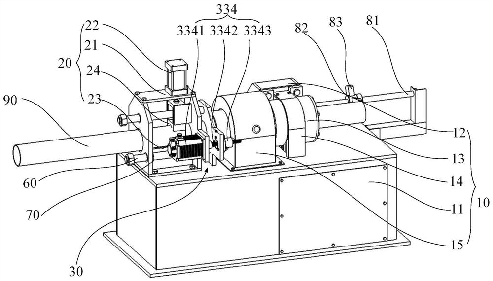
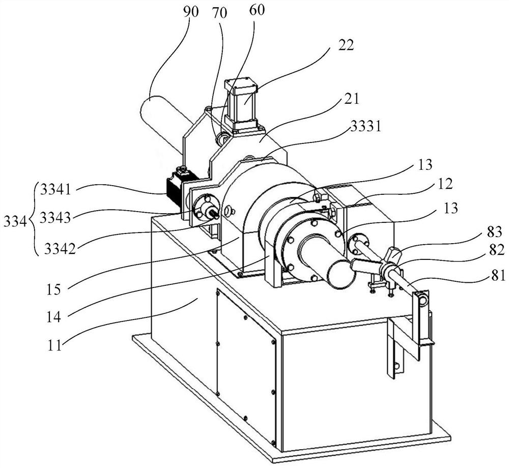
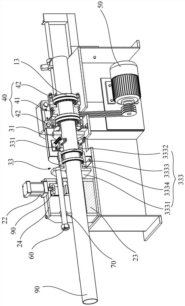
The invention provides a cutting machine. The cutting machine comprises a rack, a clamping mechanism, a hob device, a driving wheel and a power device. The hob device comprises a cutting wheel seat, a cutting wheel assembly and a driving assembly. According to the cutting machine, a pipe is clamped on the hob device, the side wall of the pipe is tightly attached to the middle position of the cutting wheel assembly, a notch of the cutting wheel assembly is perpendicular to the pipe, then the cutting wheel seat and the driving assembly act, a blade of the cutting wheel assembly cuts the pipe wall of the pipe, the power device drives the cutting wheel assembly to integrally rotate around the pipe through the driving wheel, and continuous feeding is performed to continuously cut the pipe in a rolling mode along with pushing of the driving assembly until the pipe is cut off. Scrap iron is not formed in the pipe cutting process, and the loss amount of the pipe is reduced. The cutting wheel assembly is adopted to cut the pipe in a rolling mode, the contact mode of the blade of the cutting wheel assembly and a protruding rib inside the pipe is changed, that is, the blade is not in direct impact contact with the rib, and the damage probability of the blade is correspondingly reduced.

Description

technical field [0001] The present application relates to the field of mechanical technology, in particular to a cutting machine. Background technique [0002] During the manufacture of idler rollers for belt conveyors, it needs to be cut from the pipe according to the specified length of the idler cylinder, and then processed into a standard idler cylinder. Due to the relatively large demand for idler rollers, special cutting tools are generally used. The pipe machine cuts the pipes. Some pipe cutting machines use lathes to cut pipes, that is, use a modified bedside box to drive the pipes to rotate, and use a cutter fixed on a small carriage to cut the pipes. The pipe cutting method of the special pipe cutting machine is: fix the pipe on the bed, and use the cutter to rotate around the outer diameter of the pipe to cut off the pipe. The defects in the prior art are: the cutting knife is frequently damaged; since the steel pipe used for processing and manufacturing the idle...

Claims


Application Information

Patent Timeline
Patent Type & Authority Applications(China)
IPC IPC(8): B23Q3/06B23Q5/22B23D33/02B23D33/00
CPCB23Q3/06B23Q3/062B23Q3/064B23Q5/22B23D33/02B23D33/00
Inventor 李树森李巍
Owner 扎赉诺尔煤业有限责任公司
Learn More