Electrochromic device based on transparent metal mesh electrode
An electrochromic device and transparent metal technology, applied in instruments, nonlinear optics, optics, etc., can solve the problems of uneven discoloration of devices, low production yield of time durability, etc., to reduce the influence of ion polarization, improve the Transmittance adjustment ability to achieve electrochromic effect
- Summary
- Abstract
- Description
- Claims
- Application Information
AI Technical Summary
Problems solved by technology
Method used
Image

Examples
Embodiment 1
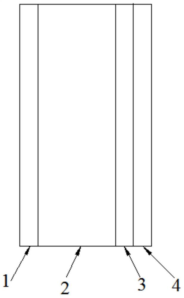
[0025] Such as figure 1 As shown, an electrochromic device based on a transparent metal mesh electrode consists of a four-layer structure, with a first layer 1, a second layer 2, a third layer 3 and a fourth layer 4 in sequence,
[0026] The first layer 1 is transparent conductive glass, which is FTO glass.
[0027] The third layer 3 is a zinc mesh, the inner diameter of the mesh is 1-1000 μm, the mesh is 5-300 mesh, and the transparency is 50% to 99%. In this embodiment, the inner diameter of the mesh is 50 μm and the mesh is 50. mesh, the transparency is 80% to 95%.
[0028] The fourth layer 4 is transparent and non-conductive glass for placing the third layer 3; the second layer 2 is a cavity for containing electrolyte; the first layer and the third layer are connected with wires.
[0029] Preparation steps:
[0030] (1) Electrolyte preparation: 0.1mol of ZnCl 2 Add to a small amount of deionized water and stir to mix, then add 1molKOH, stir while adding, the Zn(OH) gen...
Embodiment 2
[0039] The main difference from Example 1 lies in the preparation of the electrolyte: the ZnCl of 0.08mol 2 Add it into a small amount of deionized water and stir to mix, then add 1.6mol KOH, stir while adding, the Zn(OH) generated by the complexation reaction 4 2- , when the reaction is complete and the solution becomes clear, add deionized water to dilute to 1L to obtain 0.08M Zn(OH) 4 2- complex ionic electrolytes. The results show that it is reversible and the electrovariation effect is good.
Embodiment 3
[0041] The main difference from Example 1 lies in the preparation of the electrolyte: the ZnCl of 1mol 2 Add it into a small amount of deionized water and stir to mix, then add 4.1mol KOH, and stir while adding, the Zn(OH) generated by the complexation reaction 4 2- , when the reaction is complete and the solution becomes clear, add deionized water to dilute to 1L to obtain 1M Zn(OH) 4 2- complex ionic electrolytes. The results show that it is reversible and the electrovariation effect is good.
PUM
| Property | Measurement | Unit |
|---|---|---|
| The inside diameter of | aaaaa | aaaaa |
| Mesh | aaaaa | aaaaa |
| The inside diameter of | aaaaa | aaaaa |
Abstract
Description
Claims
Application Information