Wind measurement lidar device

A technology for measuring wind lidar and wind speed, which can be used in measurement devices, radio wave measurement systems, climate sustainability, etc., and can solve problems such as inability to obtain effective spectrum

Pending Publication Date: 2021-11-09
MITSUBISHI ELECTRIC CORP
View PDF1 Cites 3 Cited by
  • Summary
  • Abstract
  • Description
  • Claims
  • Application Information

AI Technical Summary

Problems solved by technology

[0004] In windmill lidar devices that measure the speed of the wind that hits the windmill installed in the nacelle of the windmill, the transmitted or received light is blocked by the blades of the windmill, and an effective frequency spectrum cannot be obtained.

Method used


Image

  • Wind measurement lidar device
  • Wind measurement lidar device
  • Wind measurement lidar device

Examples


Embodiment approach 1

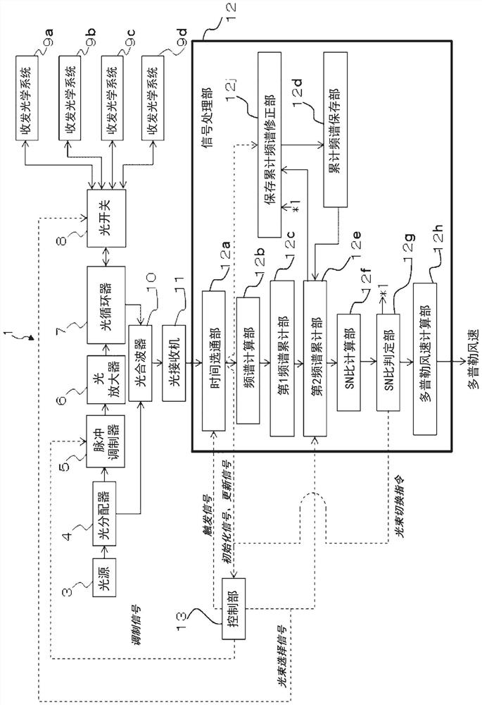
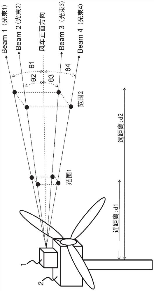
[0046] The configuration of the wind-measuring lidar device according to Embodiment 1 will be described. figure 1 It is a schematic diagram illustrating the configuration of the wind-measuring laser radar device according to the first embodiment. Wind laser radar device 1 pair of windmill 2 ( figure 2 The wind speed of the wind in front of the frontal direction of the middle diagram) is measured. The wind laser radar device 1 is mainly composed of a light source 3, an optical splitter 4, a pulse modulator 5, an optical amplifier 6, an optical circulator 7, an optical switch 8, a transceiver optical system 9a, 9b, 9c, 9d, and an optical multiplexer. 10. An optical receiver 11, a signal processing unit 12, and a control unit 13.

[0047]The wind laser radar device 1 has four transmitting and receiving optical systems 9a, 9b, 9c, and 9d. The transmission and reception optical systems 9 a , 9 b , 9 c , and 9 d respectively perform transmission and reception in beam directions ...

Embodiment approach 2

[0145] Embodiment 2 is a case in which Embodiment 1 is modified to predict the incoming wind speed and shear of a windmill. Shear refers to the rate of change of wind speed in the height direction (up and down direction) of the value of the component in the frontal direction of the windmill (called the frontal wind speed of the windmill). Figure 6 It is a schematic diagram explaining the structure of the wind-measuring laser radar apparatus concerning Embodiment 2. about Figure 6 , for the case of Embodiment 1 with the figure 1 The differences are explained.

[0146] The wind-measuring lidar device 1B has a wind speed prediction unit 16 and a beam direction storage unit 17 . The wind speed prediction unit 16 predicts an incoming wind speed and shear of the windmill based on the wind speed (Doppler wind speed) calculated by the signal processing unit 12 . The wind speed prediction unit 16 is an incoming wind information predicting unit that predicts incoming wind informat...

Embodiment approach 3

[0201] Embodiment 3 is a case in which Embodiment 2 is modified so as to include a wind direction measuring unit for measuring a wind direction at a remote place. Figure 7 It is a schematic diagram explaining the structure of the wind-measuring laser radar apparatus concerning Embodiment 3. about Figure 7 , for the case with Embodiment 2 of the Figure 6 The differences are explained. The wind laser radar device 1C has a wind direction measuring unit 18 . The wind direction measuring unit 18 measures the wind direction at a distance from the windmill. In the wind lidar device 1C, the wind speed prediction unit 16 and the wind direction measurement unit 18 constitute an incoming wind information prediction unit.

[0202] In addition, the long distance means that when the rotor diameter of the windmill is D, the distance from the windmill is 2D or more. The definition of this long distance is the distance set in Non-Patent Document 3 for the evaluation of wind turbine pow...


PUM


Abstract

With conventional methods, there is a reduction in the prediction accuracy of arriving wind information, such as arriving wind speed or wind direction. This wind measurement LIDAR device 1B: is mounted on a windmill 2; transmits, through the atmosphere, transmission light, which is pulsed laser light, in a plurality of beam directions determined with respect to the front direction of the windmill 2; and measures the wind speed in the beam directions at a plurality of distances from the windmill, from the Doppler frequency deviation with respect to transmission light of reflected light, which is the transmission light reflected by particles that move together with the atmosphere. This invention comprises: spectrum integration units 12c, 12e that obtain an integrated spectrum, which is an integration, for each wind speed measurement section consisting of a combination of a beam direction and a time section, of a spectrum obtained from split reception signals of a plurality of pulses transmitted after the wind speed was calculated previously; a wind speed calculation unit 12h that calculates a wind speed for each wind speed measurement section, for an integrated spectrum with an SN ratio that is at least a first threshold value; and an arriving wind information prediction unit 16 that, on the basis of the wind speed for each wind speed measurement section, predicts arriving wind information, namely information of arriving wind, which is wind that will arrive at the windmill 2.

Description

technical field [0001] The present disclosure relates to a wind lidar device for measuring wind speed in the atmosphere. Background technique [0002] Conventionally, a wind-measuring laser radar (LIght Detection And Ranging: Lidar) device that measures wind is known (see, for example, Comparative Documents 1 and 2 and Non-Patent Document 1). A wind lidar device emits laser light into the atmosphere, and coherently detects received light obtained by receiving light scattered and returned by aerosols in the atmosphere to generate a received signal. The frequency spectrum of the received signal is analyzed to obtain the Doppler frequency shift between the transmitted light and the received light. The Doppler shift represents the component (line-of-sight component) of the moving velocity (wind velocity) of the aerosol in the laser beam transmission direction, that is, the Doppler wind velocity (wind velocity in the line-of-sight direction). Wind lidar devices measure Doppler ...

Claims


Application Information

Patent Timeline
Patent Type & Authority Applications(China)
IPC IPC(8): G01S17/95
CPCG01S17/95Y02A90/10G01S17/10G01S17/58G01S7/4814G01S7/4917G01S17/42
Inventor 龟山俊平小竹论季梶山裕崎村武司高林干夫
Owner MITSUBISHI ELECTRIC CORP
Why Eureka
Try Eureka