Continuous grain heat pump drying system

A heat pump drying and grain technology, applied in grain drying, drying, dryer and other directions, can solve the problems of unrecycled waste heat of drying equipment, low heating efficiency and energy efficiency, and reduce system wind resistance, system The effect of small wind resistance and high heat utilization rate

Pending Publication Date: 2021-11-12
TSZJANSU CHZHEHNCHAN SIRIEHL OIL EHND FID MASHINERI KO
View PDF0 Cites 0 Cited by
  • Summary
  • Abstract
  • Description
  • Claims
  • Application Information

AI Technical Summary

Problems solved by technology

[0005] In order to solve the problem in the prior art that the air energy heat pump absorbs the heat of the external ambient air to supply heat to the drying equipment in one direction, and the waste heat of the drying equipment is not reused, resulting in relatively low heating efficiency and energy efficiency, the present invention provides a Continuous Grain Heat Pump Drying System

Method used


Image

  • Continuous grain heat pump drying system
  • Continuous grain heat pump drying system
  • Continuous grain heat pump drying system

Examples


Embodiment 1

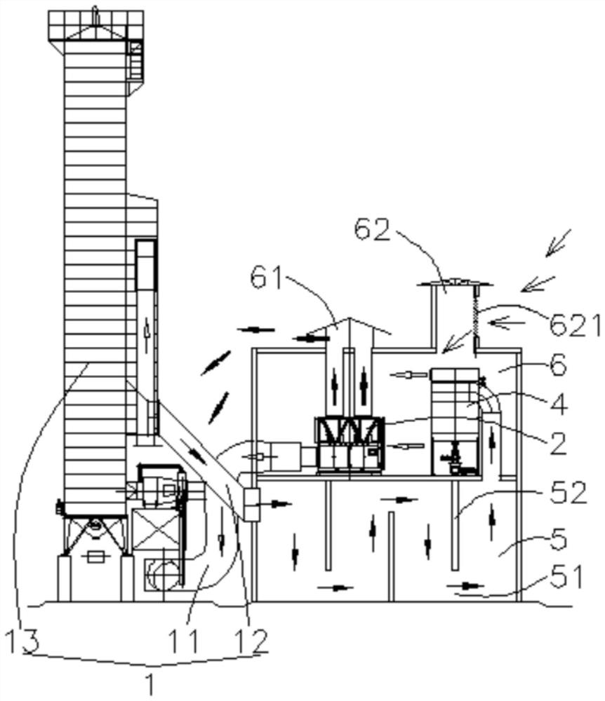
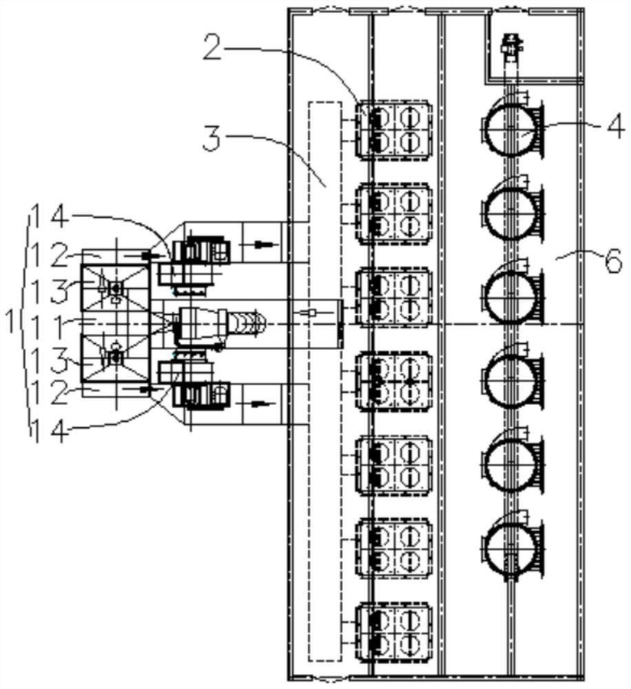
[0029] Such as figure 1 and figure 2 As shown, a continuous grain heat pump drying system includes a dryer 1, multiple air energy heat pumps 2, a total hot air pipe 3, a pulse dust collector 4, a settling chamber 5 and a hot air room 6; the hot air room 6 Set above the settling chamber 5, the air inlet of the pulse dust collector 4 communicates with the upper part of the settling chamber 5, the air outlet of the pulse dust remover 4 communicates with the hot air room 6, and the air energy heat pump 2 is arranged in the hot air room 6, the air inlet of the air energy heat pump 2 is connected to the hot air room 6, and the hot air outlets of multiple air energy heat pumps 2 are connected to the total hot air pipe 3, and the hot air outlet of the total hot air pipe 3 is connected to the oven. The hot air channel 11 of the dryer 1 is connected, and the exhaust gas channel 12 of the dryer 1 is communicated with the settling chamber 5; The air cap 61 communicates with the cold ai...

Embodiment 2

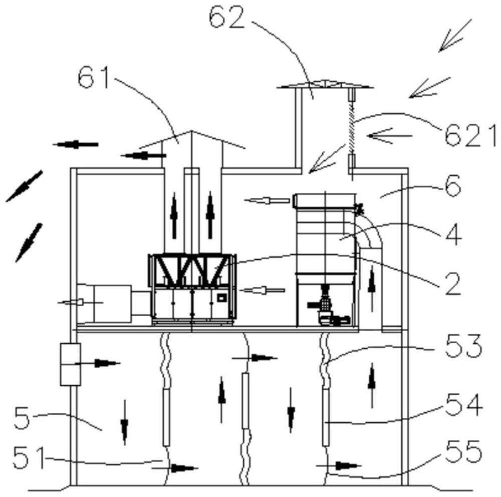
[0039] Such as image 3 As shown, in this embodiment, the difference from Embodiment 1 is that the material blocking structure includes a flexible blocking section 53 and a rigid blocking section 54 connected in sequence, and the flexible blocking section 53 is fixedly connected to the settling chamber 5, so The rigid retaining section 54 is fixedly connected to the settling chamber 5 through a rope 55, and the rope 55 is located at the corresponding airflow gap 51; the material of the flexible retaining section 53 in this embodiment is rubber, plastic, foam or non-woven fabric . The flexible retaining section 53 of this embodiment combined with the rigid retaining section 54 has a certain degree of flexibility and a certain supporting rigidity. Better impact on the material retaining structure and deceleration, and the cost of the flexible retaining section 53 is relatively low; The structure is better to reduce the dust speed, shake off the dust effectively, and further im...


PUM


Abstract

The invention belongs to the technical field of grain drying equipment, and particularly relates to a continuous grain heat pump drying system. The system comprises a dryer, a plurality of air energy heat pumps, a main hot air pipe, a pulse dust collector, a settling chamber and a hot air room. The hot air room is arranged above the settling chamber, an air inlet of the pulse dust collector communicates with the upper portion of the settling chamber, an air outlet of the pulse dust collector communicates with the hot air room, the air energy heat pumps are arranged in the hot air room, and hot air outlets of the plurality of air energy heat pumps all communicate with the main hot air pipe. A hot air outlet of the main hot air pipe communicates with a hot air channel of the dryer, and a waste gas channel of the dryer communicates with the settling chamber. The hot air room is provided with an exhaust air cap and an air supply air cap which communicate with the outside, the exhaust air cap communicates with cold air outlets of the air energy heat pumps, the air supply air cap communicates with the hot air room, and an air inlet of the air supply air cap is higher than a cold air outlet of the exhaust air cap.

Description

technical field [0001] The invention belongs to the technical field of grain drying equipment, in particular to a continuous grain heat pump drying system. Background technique [0002] Ensuring food security is the top priority of our country, and it is also the top priority of economic and social development. As our country fully promotes the comprehensive mechanization of agricultural production, and increases investment in key links of agricultural production and improves the mechanical level of weak links, it can effectively improve the overall agricultural production capacity and promote the comprehensive and healthy development of agricultural production. Since 2011, grain drying equipment has been included in the national agricultural machinery subsidy catalog and has been subsidized. The domestic grain drying equipment has grown rapidly at an average annual rate of 150%. The shortcomings of my country's agricultural mechanization, the development of my country's gra...

Claims


Application Information

Patent Timeline
Patent Type & Authority Applications(China)
IPC IPC(8): F26B21/00F26B21/04F26B23/00A23B9/08
CPCF26B21/002F26B21/003F26B21/004F26B21/04F26B23/005A23B9/08F26B2200/06Y02A40/90Y02P60/85
Inventor 张正礼史文杰吕云凯腾闯王曙光
Owner TSZJANSU CHZHEHNCHAN SIRIEHL OIL EHND FID MASHINERI KO
Why Eureka
Try Eureka