
Low-voltage power distribution network tail end low-voltage treatment parallel compensation device

A low-voltage distribution network and compensation device technology, applied in circuit devices, AC network voltage adjustment, electrical components, etc., can solve the problems of large voltage drop, long construction period, and large investment in long-distance AC transmission lines, and achieve comprehensive savings. The effect of retrofitting cost, reducing equipment loss and convenient installation

Pending Publication Date: 2021-11-12
QINGDAO TOPSCOMM COMM +1
View PDF7 Cites 0 Cited by
  • Summary
  • Abstract
  • Description
  • Claims
  • Application Information

AI Technical Summary

Problems solved by technology

This method has problems such as long construction period, large investment and high cost, and it is difficult to obtain a good return on investment. With the increase of high-power loads in residents' homes, it is likely that low-voltage problems will occur again due to the continuous increase in residential consumption.
[0005] 2) The series compensation scheme is adopted to rectify AC power into DC power through power electronic conversion technology, and the original AC transmission line is converted into a DC transmission line to reduce line loss. On the user side, the DC power is converted into AC power through power electronic conversion technology. This method can solve the problem of large voltage drop on long-distance AC transmission lines to a certain extent, but it is limited by the capacity of the equipment and cannot flexibly adapt to the increasing power demand of users, and because of the series connection method, it will affect the original line Carrier communication and meter reading functions

Method used


Image

  • Low-voltage power distribution network tail end low-voltage treatment parallel compensation device
  • Low-voltage power distribution network tail end low-voltage treatment parallel compensation device
  • Low-voltage power distribution network tail end low-voltage treatment parallel compensation device

Examples


Embodiment Construction

[0045] In order to make the object, technical solution and advantages of the present invention clearer, the present invention will be further described in detail below in conjunction with the accompanying drawings and embodiments. It should be understood that the specific embodiments described here are only used to explain the present invention, not to limit the present invention.

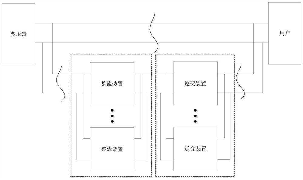
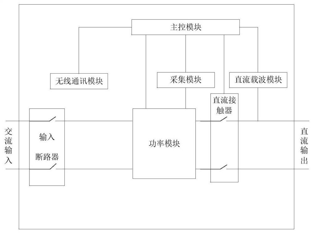
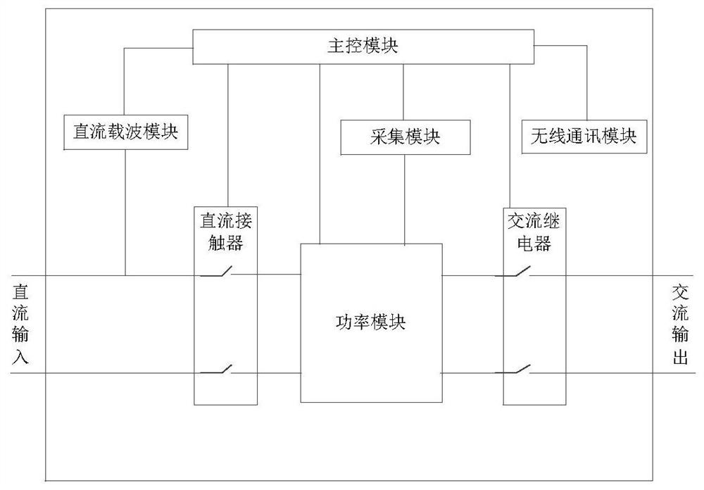
[0046] A parallel compensation device for low-voltage control at the end of a low-voltage distribution network of the present invention, such as figure 1 As shown, it includes a rectifier device and an inverter device. The rectifier device is close to the transformer side, and the inverter device is close to the user side. The AC branch is drawn on the transformer side as the input of the rectifier device. The rectifier device rectifies the AC output from the transformer into DC power, and passes through The separate DC transmission line is sent to the inverter device, which inverts the DC power in...


PUM


Abstract

The invention discloses a low-voltage power distribution network tail end low-voltage treatment parallel compensation device. The device comprises a rectifying device and an inversion device, the input side of the rectifying device is connected with the output side of a power distribution network transformer, three-phase alternating current is rectified into direct current, and the output side of the rectifying device is connected with the input side of the inversion device through an independent direct current transmission cable; and the input side of the inversion device is connected with the output side of the rectifying device through an independent direct current transmission cable to invert direct current into alternating current, and the output side of the inversion device is connected with an original alternating current transmission cable in parallel. According to the invention, through the AC-DC-AC conversion technology, a parallel connection mode is adopted to compensate the user power demand before and after the original AC power transmission parallel connection point, the problem of low end voltage caused by line voltage drop in high-power long-distance AC power transmission is solved, and the end user voltage quality is improved.

Description

technical field [0001] The invention relates to the technical field of low-voltage power distribution, in particular to a parallel compensation device for low-voltage control at the end of a low-voltage power distribution network. Background technique [0002] With the rapid development of my country's economy and the continuous improvement of residents' living standards, the electricity consumption of residents has also increased. The requirements for the power quality of distribution networks have become one of the important assessment items for power supply companies. However, in some relatively remote mountainous areas or rural areas, the problem of terminal low voltage caused by long power supply radius, thin transmission cable diameter and fluctuations in residential electricity load is very prominent, and the terminal voltage cannot meet the supply voltage specified in the national standard The deviation is +7% and -10% of the nominal voltage. At the same time, the co...

Claims


Application Information

Patent Timeline
IPC IPC(8): H02J3/12H02J3/38H02J13/00
CPCH02J3/12H02J3/38H02J13/00001H02J13/00007H02J13/00022Y02E40/70Y02E60/00Y02B90/20Y04S10/12Y04S40/121Y04S40/126
Inventor 范建华徐鹏飞李健勋张颖佳王亮张作超李广琛刘长鑫
Owner QINGDAO TOPSCOMM COMM
Learn More