
Controllable optical storage device and method based on photonic crystal dynamic microcavity

A technology of photonic crystals and photonic crystal waveguides, which is applied in the field of controllable optical storage devices, can solve problems such as technical complexity, application limitations, and demanding experimental conditions, and achieve simple manufacturing processes, high-efficiency capture, great flexibility, and plasticity Effect

Active Publication Date: 2021-11-16
SOUTH CHINA UNIV OF TECH
View PDF5 Cites 0 Cited by
  • Summary
  • Abstract
  • Description
  • Claims
  • Application Information

AI Technical Summary

Problems solved by technology

These dynamic Q-switching methods, whether based on the interference effect of phase modulation or the electromagnetic induction-like transparency effect based on multi-microcavity resonance frequency modulation, involve very complicated technologies and require very strict experimental conditions, so their application limited

Method used


Image

  • Controllable optical storage device and method based on photonic crystal dynamic microcavity
  • Controllable optical storage device and method based on photonic crystal dynamic microcavity
  • Controllable optical storage device and method based on photonic crystal dynamic microcavity

Examples


Embodiment Construction

[0036] In order to enable those skilled in the art to better understand the solutions of the present application, the technical solutions in the embodiments of the present application will be clearly and completely described below in conjunction with the drawings in the embodiments of the present application. Apparently, the described embodiments are only some of the embodiments of this application, not all of them. Based on the embodiments in this application, all other embodiments obtained by those skilled in the art without making creative efforts belong to the scope of protection of this application.

[0037] Reference in this application to an "embodiment" means that a particular feature, structure, or characteristic described in connection with the embodiment can be included in at least one embodiment of the present application. The occurrences of this phrase in various places in the specification are not necessarily all referring to the same embodiment, nor are separate...


PUM

PropertyMeasurementUnit
wavelengthaaaaaaaaaa
refractive indexaaaaaaaaaa

Abstract

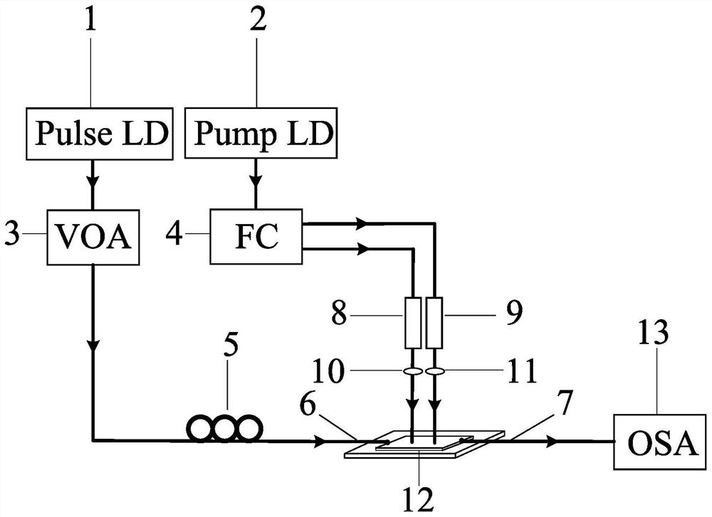
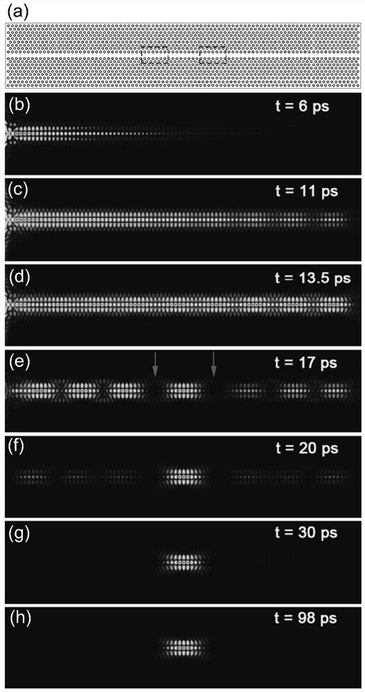
The invention discloses an optical storage device and method based on a photonic crystal dynamic microcavity. Optical pumping of dynamic refractive index modulation regions at two ends of a capture region is carried out when pulse signal light is transmitted along a photonic crystal waveguide and passes through a preset capture region, the refractive indexes of the modulation regions at the two ends are instantly reduced, two optical barriers are formed, pulse signal light is captured in a photonic crystal dynamic microcavity between two light barriers, and light storage is achieved. And when the pulse signal light is stored for a certain time and needs to be released at a certain moment, optical pumping of any one of the refractive index dynamic modulation areas at the two ends of the capture area is stopped instantly, so that the optical barrier at the position disappears and a release channel is formed, and the stored pulse signal light is quickly released from the channel. The invention further discloses an optical storage device based on the photonic crystal dynamic microcavity. According to the invention, the pulse signal light freely transmitted along the photonic crystal waveguide can be actively captured and can be released along a given direction.

Description

technical field [0001] The invention belongs to the technical field of photonic crystals, and in particular relates to a controllable optical storage device and method based on photonic crystal dynamic microcavities. Background technique [0002] The controllable storage and release of light is an important and basic problem in all-optical information processing, and has extremely broad application prospects in all-optical communication, quantum computing, and optical circuit integration. [0003] In order to realize optical storage, the key is to slow down or even stop the speed of light in the optical transmission medium. In recent years, with the development of micro-nanophotonic technology, people have successively realized slow light with controllable light speed in nonlinear optical fibers and photonic crystal waveguides. The former is mainly realized by means of Raman scattering and Brillouin scattering to generate strong dispersion at the nonlinear gain of the fiber...

Claims


Application Information

Patent Timeline
Patent Type & Authority Applications(China)
IPC IPC(8): G11B7/2403G11B7/24062G11B7/24
CPCG11B7/24G11B7/24062G11B7/2403
Inventor 李潮吴俊芳
Owner SOUTH CHINA UNIV OF TECH
Learn More