Rotor punching sheet group, rotor iron core, rotor and motor

A technology of rotor punching and rotor core, which is applied in the field of rotors and motors, rotor cores, and rotor punching groups, can solve the problems that do not reflect the advantages of the tangential magnetic circuit structure, and reduce the risk of magnetic steel falling off. Save dosage, good effect

Inactive Publication Date: 2021-11-16
天津众科科技发展有限公司
View PDF10 Cites 0 Cited by
  • Summary
  • Abstract
  • Description
  • Claims
  • Application Information

AI Technical Summary

Problems solved by technology

Therefore, in order to make the motor produce the torque required by the design, the amount of magnetic steel used is not necessarily s

Method used


Image

  • Rotor punching sheet group, rotor iron core, rotor and motor
  • Rotor punching sheet group, rotor iron core, rotor and motor
  • Rotor punching sheet group, rotor iron core, rotor and motor

Examples


Embodiment Construction

[0027] The present invention will be further described below in conjunction with the accompanying drawings and embodiments.

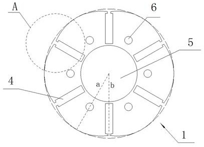
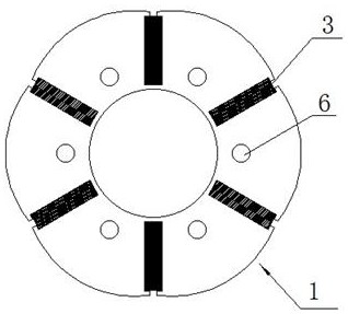
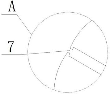
[0028] Such as Figure 1-7 As shown, a rotor punching set includes a first rotor punching 1 and a second rotor punching 2, and the centers of the first rotor punching 1 and the second rotor punching 2 both form a shaft hole 5; preferably , the inner diameter and outer diameter of the first rotor punching piece 1 and the second rotor punching piece 2 are respectively the same.

[0029] A plurality of permanent magnet slots 4 are formed on the first rotor punch 1 and the second rotor punch 2 , and the permanent magnet slots 4 extend radially along the rotor punch and are center-symmetrically distributed on the rotor punch. Such as figure 1 , 4 As shown, preferably, six permanent magnet slots 4 are respectively formed on the first rotor punching piece 1 and the second rotor punching piece 2, and the six permanent magnet slots 4 are symmetrically distrib...


PUM


Abstract

The invention discloses a rotor punching sheet group, a rotor iron core, a rotor and a motor. The rotor punching sheet group comprises a first rotor punching sheet and a second rotor punching sheet, a plurality of permanent magnet grooves are formed in the first rotor punching sheet and the second rotor punching sheet, and the permanent magnet grooves extend along the radial direction of the rotor punching sheets and are distributed on the rotor punching sheets in a central symmetry manner; an outer diameter magnetic isolation notch is formed between the outer end of the permanent magnet groove on the first rotor punching sheet and the outer diameter of the first rotor punching sheet; and an inner diameter magnetic isolation notch is formed between the inner end of the permanent magnet groove on the second rotor punching sheet and the inner diameter of the second rotor punching sheet. The rotor iron core is formed by laminating a plurality of the first rotor punching sheets and the second rotor punching sheets. The rotor comprises the rotor iron core and a permanent magnet, and the permanent magnet is arranged in the rotor iron core. The motor comprises the rotor. Two rotor punching sheets are laminated, so that the problem of magnetic leakage of rotor magnetic steel is effectively solved on the basis of ensuring the mechanical strength of the rotor, the magnetic leakage amount is reduced, and the use amount of the magnetic steel is saved.

Description

technical field [0001] The invention relates to the technical field of motor manufacturing, in particular to a rotor punching set, a rotor iron core, a rotor and a motor. Background technique [0002] Due to its high efficiency and high power density, permanent magnet synchronous motors are widely used in new energy electric vehicles as a driving power source for vehicles. [0003] The rotor structure of the permanent magnet synchronous motor is diverse. The magnetic steel is placed inside the rotor core, and the reluctance torque generated by the asymmetry of the rotor core improves the power density of the permanent magnet synchronous motor. At present, the commonly used rotor magnetic steel forms are divided into radial magnetic circuit structure and tangential magnetic circuit structure composed of "one" type, "V" type and "V-one" type. For the radial magnetic circuit structure, the magnetic flux generated by the outer surface of the magnet interacts with the magnetic f...

Claims


Application Information

Patent Timeline
IPC IPC(8): H02K1/27
CPCH02K1/27H02K1/2766
Inventor 陈学永高鹏
Owner 天津众科科技发展有限公司
Why Eureka
Try Eureka