Underground coal mine universal type self-power-generating device

A general-purpose, self-generating technology, applied in the field of electronic information, can solve problems such as difficult maintenance in the later period, potential safety hazards, and a large number of cables, and achieve the effect of reducing damage to sensors, improving convenience, and strong scalability.

Pending Publication Date: 2021-11-16
CHINA COAL TECH & ENG GRP CHONGQING RES INST CO LTD
View PDF5 Cites 3 Cited by
  • Summary
  • Abstract
  • Description
  • Claims
  • Application Information

AI Technical Summary

Problems solved by technology

At present, the sensor power supply on the drilling rig is still provided by the explosion-proof electromagnetic starter. During the low-voltage long-distance transmission process, the line loss is high, the number of cables is large, easy to be entangled, difficult to maintain later, and there are potential safety hazards
Due to the requirements for intrinsically safe circuits in underground coal mines, there is no self-generating device suitable for underground coal mines on the market.

Method used


Image

  • Underground coal mine universal type self-power-generating device
  • Underground coal mine universal type self-power-generating device

Examples


Embodiment 1

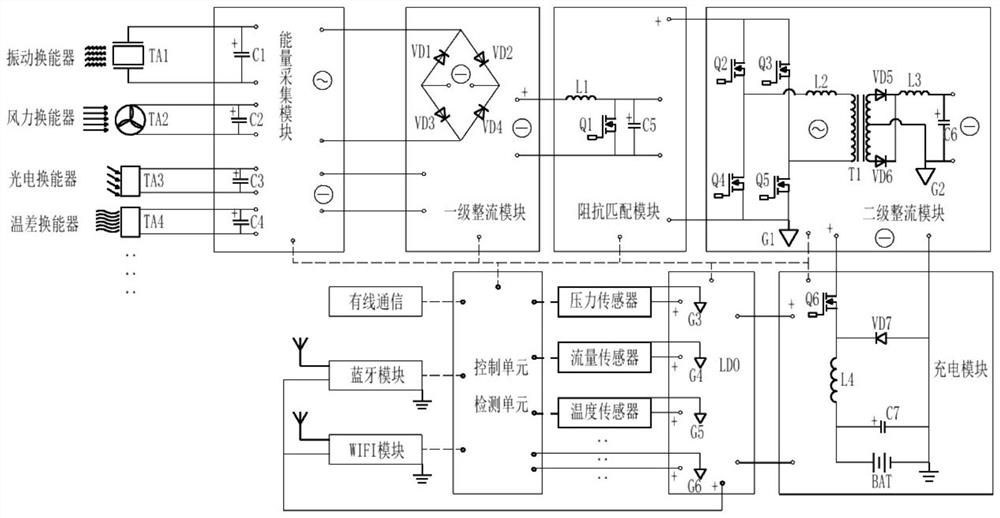
[0059] Embodiment 1: A vibration self-generating device composed of a piezoelectric crystal oscillator.

[0060] When the mechanical equipment is working, the magnetic seat of the self-generating device is adsorbed on the surface of the vibrating equipment (not limited to motors, mud pumps, drilling rig fuselages, etc.). The mechanical energy transducing unit receives the vibration energy and converts the mechanical energy into alternating current through the piezoelectric sensor. Since it is an AC transducer, the electric energy passes through the first diode VD1, the second diode VD2, and the first diode VD2 in the primary rectification module. A full-bridge AC / DC circuit composed of three diodes VD3 and a fourth diode VD4 is converted into direct current. After passing through the impedance matching circuit, it flows into the secondary rectification circuit, passes through the second MOS transistor Q2, the third MOS transistor Q3, and the fourth MOS transistor Q4 to form a ...

Embodiment 2

[0061] Embodiment 2: A temperature difference self-generating device connected with a temperature difference energy collector.

[0062] When the equipment is working, the temperature of the hydraulic oil rises due to being compressed, and the magnetic seat of the self-generating device is adsorbed on the surface of the radiator. The energy conversion unit receives the high temperature on the surface of the radiator and the low temperature in the environment to form a temperature gradient, thereby generating an electromotive force. Because it is a DC transducer, the electric energy directly flows into the impedance matching module through the first-stage rectification module. After passing through the impedance matching circuit, it flows into the secondary rectification circuit, passes through the second MOS transistor Q2, the third MOS transistor Q3, and the fourth MOS transistor Q4 to form a DC / AC circuit, passes through the second inductor L2, and the transformer T1 performs...


PUM


Abstract

The invention relates to an underground coal mine universal type self-power-generating device, which belongs to the technical field of electronic information. The device comprises a transduction unit, a circuit rectification unit, a control unit, a detection unit, an energy storage unit, an electric energy output module and a signal output module. The transduction unit is sequentially connected with the circuit rectification unit, the energy storage unit and the electric energy output module; the detection unit is respectively connected with the circuit rectification unit, the energy storage unit and the electric energy output module and is responsible for detecting the output voltage of each unit and module in real time; the signal output module is connected with the control unit; the circuit rectification unit is used for rectifying the current waveform generated by the transduction unit; the energy storage unit uses a rechargeable battery and is used for supplying power to the sensor and storing redundant electric energy converted by the transduction unit; and the detection unit detects the voltage of the energy storage unit and feeds back a signal to the control unit for judging charging and discharging logic. The device can be installed nearby a sensor, each sensor can work, and meanwhile wire harnesses are reduced.

Description

technical field [0001] The invention belongs to the technical field of electronic information, relates to the technical fields of electrical equipment and electrical engineering, and in particular relates to a general-purpose self-generating device for underground coal mines. Background technique [0002] At present, coal mine underground drilling equipment is gradually realizing automation and intelligence. Therefore, the drilling rig needs to be equipped with a large number of sensors, and most of these sensors are low-voltage and weak-current devices. At present, the sensor power supply on the drilling rig is still provided by the explosion-proof electromagnetic starter. During the low-voltage long-distance transmission process, the line loss is high, the number of cables is large, easy to be entangled, difficult to maintain later, and there are potential safety hazards. Due to the requirements for intrinsically safe circuits in underground coal mines, there is no self-g...

Claims


Application Information

Patent Timeline
Patent Type & Authority Applications(China)
IPC IPC(8): H02N2/18H02N11/00H02S10/12H02J7/32H02J7/02
CPCH02N2/186H02N11/002H02S10/12H02J7/32H02J7/02Y02E10/50
Inventor 闫保永王国震曹柳阳廷军王杰陈泽平孟祥辉朱利民刘思聪张先韬郝少楠赵胜天郭向勇张晓泽薛赞叶强波
Owner CHINA COAL TECH & ENG GRP CHONGQING RES INST CO LTD
Why Eureka
Try Eureka