Heavy natural gas engine combustion system

A combustion system and natural gas technology, applied in the direction of gaseous engine fuel, fuel system, engine components, etc., can solve the problems of adverse effects on thermal efficiency, low flame propagation rate of natural gas, large heat transfer loss, etc., and achieve good macroscopic and large-scale flow retention capacity , Improve the turbulent kinetic energy in the cylinder and accelerate the propagation speed

Pending Publication Date: 2021-11-23
TIANJIN UNIV
View PDF0 Cites 5 Cited by
  • Summary
  • Abstract
  • Description
  • Claims
  • Application Information

AI Technical Summary

Problems solved by technology

[0002] Heavy-duty natural gas engines have advantages in realizing low-carbon and clean combustion. However, due to the relatively large space scale of the combustion chamber of heavy-duty engines and the low flame propagation rate of natural gas, the knocking tendency is increased, which limits the increase in compression ratio. These factors have a great impact on thermal efficiency. bring adverse effects
At the same time, because the stoichiometric air-fuel ratio or slightly lean mixture is usually used, the combustion temperature in the cylinder is high. On the one hand, the heat transfer loss is large, which affects the thermal efficiency. On the other hand, the engine heat load is high, which affects the reliability.
In addition, heavy-duty natural gas engines mostly use aluminum alloy pistons, which have large heat transfer losses, poor mechanical load and thermal load bearing capacity, and are difficult to meet reliability requirements

Method used


Image

  • Heavy natural gas engine combustion system
  • Heavy natural gas engine combustion system
  • Heavy natural gas engine combustion system

Examples


Embodiment Construction

[0016] In order to further illustrate the functional structure of the present invention, the present invention will be described in detail below in conjunction with the accompanying drawings and preferred embodiments. Obviously, the described embodiments are only some embodiments of the present invention, rather than all embodiments, and the protection scope of the present invention It is not limited by the specific implementation manner.

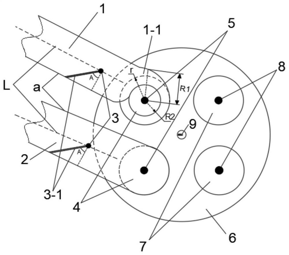
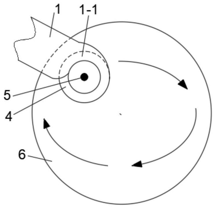
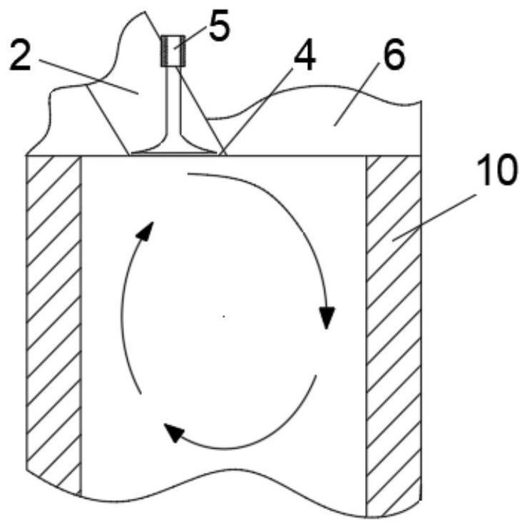
[0017] Such as figure 1 As shown, the heavy-duty natural gas engine combustion system provided by the present invention includes a cylinder 10 and a cylinder head 6 covered on the cylinder. The valve 4 communicates with the interior of the cylinder 10, the intake valve 5 is installed on the valve seat, the intake valve 4 is located in the entire valve seat, and the two exhaust port inlets 7 are installed on the cylinder head 6 through The exhaust valve 8 communicates with the inside of the cylinder 10, a spark plug device 9 is installed at...


PUM


Abstract

The invention discloses a heavy natural gas engine combustion system. The system comprises an air cylinder and a cylinder cover covering the air cylinder, the cylinder cover is provided with a composite air inlet channel composed of a vortex air inlet channel and a straight tumble air inlet channel and communicates with the interior of the air cylinder through an air inlet gate provided with an air inlet valve, the air inlet valve is arranged on a valve seat, The air inlet gate is located in the whole valve seat, two exhaust passage inlets communicate with the interior of the air cylinder through exhaust valves arranged on the cylinder cover, a spark plug device is installed in the center of the bottom face of the cylinder cover, a steel piston is arranged in the cylinder cover, and the bottom face of the cylinder cover, the inner wall face of the air cylinder and the top face of the piston define a space which serves as a necking-down type combustion chamber, and gas supply and injection systems are respectively arranged on the two gas inlet channels or the bottom surface of the cylinder cover. The system is simple and compact in structure and convenient in manufacturing and assembly, low heat dissipation is achieved through the steel piston, meanwhile, inlet air flow can form oblique axis vortex around the central axis of the cylinder through the composite air inlet channel, turbulent kinetic energy in the cylinder is improved, and then heat efficiency is improved.

Description

technical field [0001] The invention relates to an engine combustion system, more precisely, relates to a heavy-duty natural gas engine combustion system. Background technique [0002] Heavy-duty natural gas engines have advantages in achieving low-carbon and clean combustion. However, due to the relatively large space scale of the combustion chamber of heavy-duty engines and the low flame propagation rate of natural gas, the knocking tendency is increased, which limits the increase in compression ratio. These factors have a great impact on thermal efficiency. bring adverse effects. At the same time, because the stoichiometric air-fuel ratio or slightly lean mixture is usually used, the combustion temperature in the cylinder is high. On the one hand, the heat transfer loss is large, which affects the thermal efficiency. On the other hand, the engine heat load is high, which affects the reliability. In addition, heavy-duty natural gas engines mostly use aluminum alloy piston...

Claims


Application Information

Patent Timeline
Patent Type & Authority Applications(China)
IPC IPC(8): F02B23/08F02B23/10F02B43/10F02B31/06F02B31/08F02F1/24F02F1/42F02F3/00
CPCF02B23/08F02B43/10F02B31/06F02B31/082F02B31/085F02F1/242F02F1/4228F02F1/4235F02F3/0092F02B2023/108F02B2043/103Y02T10/12Y02T10/30
Inventor 郑尊清潘成尧命发赵旭敏王浒刘海峰
Owner TIANJIN UNIV
Why Eureka
Try Eureka