
Ultralow-load sulfur recovery system and process

A sulfur recovery and loading technology, which is applied in the direction of sulfur compounds, sulfur preparation/purification, inorganic chemistry, etc., can solve the problems of burnout of the burner, tempering of the acid gas burner, etc., and achieve high flame turbulence and strong combustion , good mixing effect

Active Publication Date: 2021-11-26
LUOYANG RUICHANG PETROCHEM EQUIP
View PDF7 Cites 0 Cited by
  • Summary
  • Abstract
  • Description
  • Claims
  • Application Information

AI Technical Summary

Problems solved by technology

[0005] The purpose of the present invention is to propose an ultra-low-load sulfur recovery system and process to solve the problem in the prior art that the acid gas burner is backfired due to too low acid gas load, which in turn leads to burnout of the burner

Method used


Image

  • Ultralow-load sulfur recovery system and process
  • Ultralow-load sulfur recovery system and process

Examples


Embodiment 1

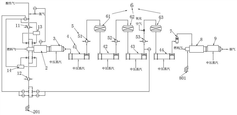
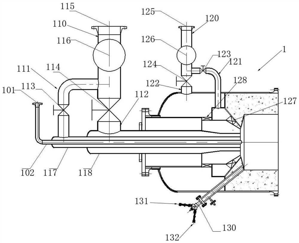
[0065] This embodiment proposes an ultra-low load sulfur recovery system, such as Figure 1-2 As shown, the ultra-low load sulfur recovery system includes a sequentially connected acid gas combustion unit and a tail gas treatment unit, the acid gas combustion unit includes a sequentially connected combustion furnace 2 and a combustion waste pot 3, and the tail gas treatment unit includes a condensing device assembly 4, reheater assembly 5, reactor assembly 6, catcher 7, incinerator 8 and incineration waste pot 9, first burner 1 is set on said burner 2, and said first burner 1 is provided with a two-stage acid gas passage 110 and a two-stage combustion air passage 120, and an acid gas spray gun assembly is arranged at the outlet end of the two-stage acid gas passage 110.

[0066] The ultra-low-load sulfur recovery system and process described in this embodiment can meet the needs of normal operation when the acid gas is 10%-30% of the design value, and the sulfur recovery rate ...

Embodiment 2

[0134] This embodiment proposes an ultra-low-load sulfur recovery process. The ultra-low-load sulfur recovery process uses an ultra-low-load sulfur recovery system as described in Example 1. The ultra-low-load sulfur recovery process includes the following steps:

[0135] S100: Acid gas and combustion-supporting air enter the combustion furnace 2 sequentially through the first burner 1 for combustion, and the high-temperature process gas generated by combustion is condensed in the combustion waste pot 3 to obtain liquid sulfur and recovered;

[0136] S200: The process gas condensed by burning the waste pot 3 enters the condensers, reheaters and reactors at all levels, and carries out the Claus reaction under the action of a suitable catalyst in the reactor to recover liquid sulfur. And the generated process gas is condensed through the condenser, and the deeply condensed process gas is carried out sulfur separation through the catcher 7;

[0137] S300: The tail gas after passi...


PUM


Abstract

The invention provides an ultralow-load sulfur recovery system and process, the ultralow-load sulfur recovery system comprises an acid gas combustion unit and a tail gas treatment unit which are connected in sequence, and the acid gas combustion unit comprises a combustion furnace and a combustion waste boiler which are connected in sequence; wherein the tail gas treatment unit comprises a condenser assembly, a reheater assembly, a reactor assembly, a trap, an incinerator and an incineration waste heat boiler, a first combustor is arranged on the combustion furnace, a two-stage acid gas channel and a two-stage combustion-supporting air channel are arranged on the first combustor, and an acid gas spray gun assembly is arranged at the outlet end of the two-stage acid gas channel. According to the ultra-low load sulfur recovery system, two stages of acid gas channels are arranged on the first combustor, so that proper acid gas channels can be conveniently selected according to different acid gas flows to prevent the first combustor from tempering, and meanwhile, the operation regulation ratio of the first combustor can be increased, and the work flexibility is improved; meanwhile, two stages of combustion-supporting air channels are arranged on the first combustor, so that the combustion effect of the first combustor is guaranteed.

Description

technical field [0001] The invention relates to the field of sulfur recovery, in particular to an ultra-low-load sulfur recovery system and process. Background technique [0002] Sulfur recovery unit is used to process H2O produced by coal chemical industry, petrochemical industry and fine chemical industry. 2 S acid gas, the main device for by-product sulfur. Acid gas treatment capacity is the most important technical parameter in the design of sulfur recovery unit. Under normal design conditions, the treatment capacity of acid gas is required to be 30%-120% of the design value. Or affected by the sulfur content in the raw materials of upstream devices, the operating load of some sulfur recovery devices has been lower than 30% for a long time, and basically maintained between 10% and 20%. This phenomenon is particularly prominent in coal chemical, fine chemical and other industries. [0003] The long-term low-load operation of the sulfur recovery unit will have adverse ef...

Claims


Application Information

Patent Timeline
Patent Type & Authority Applications(China)
IPC IPC(8): C01B17/04
CPCC01B17/0421C01B17/0447Y02P20/129
Inventor 孙东旭刘颖蒋松王丽洁高建峰
Owner LUOYANG RUICHANG PETROCHEM EQUIP
Learn More