
Hazardous waste incineration system and operation process thereof

An incinerator and waste heat boiler technology, applied in incinerators, combustion methods, combustion types, etc., can solve the problems of large increase in fly ash amount, corrosion of back-end equipment, increase in processing costs, etc., and achieve low system operating costs and dust content. The effect of reducing and reducing fly ash production

Pending Publication Date: 2021-11-26
EVERBRIGHT ENVIRONMENTAL TECH CHINA CO LTD +2
View PDF3 Cites 0 Cited by
  • Summary
  • Abstract
  • Description
  • Claims
  • Application Information

AI Technical Summary

Problems solved by technology

[0008] (1) Use a quenching tower to cool down to reduce the generation of dioxins. However, if water spraying is used for quenching, a large amount of waste heat of flue gas will be lost, and it will cause corrosion and blockage of back-end equipment
If the economizer mentioned in CN211345334U is adopted, compared with the high efficiency of direct evaporative heat transfer, the heat transfer efficiency of the economizer is relatively low, and it is extremely difficult to quickly cool down the flue gas within 1s, and the flue gas after cooling will be extremely difficult. Moisture content has not increased, but the corrosiveness is still high
[0009] (2) The emission reduction of dioxins is not complete. The quenching tower can only reduce the regeneration of dioxins, but the amount of dioxins after quenching is still relatively high
[0010] (3) The emission reduction effect of conventional technologies is relatively poor. my country's current hazardous waste gas emission standards are far below similar domestic waste incineration standards. In the future, it is bound to face the need for standard upgrading and transformation
And if the system of CN109185897B is adopted, the overall process chain is too lengthy, and problems such as energy utilization, corrosion, blockage, etc. cannot be solved
[0011] (4) The stability of the existing technology is insufficient. Due to the complex and changeable nature of hazardous waste, the concentration of flue gas pollutants varies greatly, and the existing technology is obviously unable to withstand large fluctuations in pollutants. For example, for high-chlorine hazardous waste, Just need to adopt the more efficient system of this kind of CN109185897B similar
[0012] (5) The use of dry deacidification leads to a large increase in the amount of fly ash, and the fly ash collected by a single dust collector contains both dust in the flue gas and deacidification by-products, which can only be identified as hazardous waste, and the treatment cost is high increase

Method used


Image

  • Hazardous waste incineration system and operation process thereof
  • Hazardous waste incineration system and operation process thereof

Examples


Embodiment 1

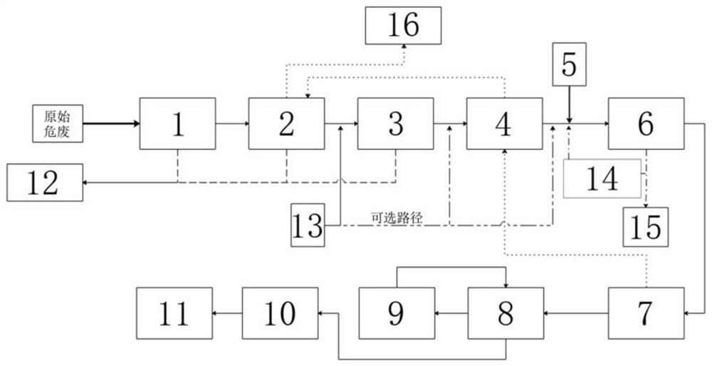
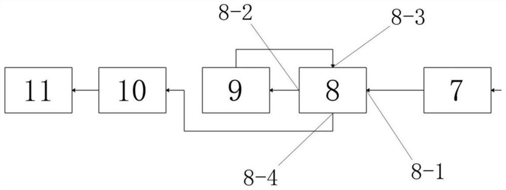
[0055] A hazardous waste incineration system, such as figure 1 As shown, including hazardous waste incinerator 1, primary waste heat boiler 2, high temperature dust collector 3, secondary waste heat boiler 4, dry deacidification system 5, medium and high temperature dust removal-denitration and dioxin removal device 6, economizer 7 , GGH flue gas heat exchanger 8, wet deacidification system 9, induced draft fan 10, chimney 11.

[0056] The hazardous waste incinerator 1 is sequentially connected to the first-stage waste heat boiler 2, the high-temperature dust collector 3, the second-stage waste heat boiler 4, the medium-high temperature dust removal-denitration and dioxin removal device 6, and the The economizer 7 and the GGH flue gas heat exchanger 8 are described.

[0057] The dry deacidification system 5 is arranged between the secondary waste heat boiler 4 and the medium-high temperature dust removal-denitration and dioxin removal device 6 through a flue.

[0058] Such a...

Embodiment 2

[0068] Adopt the hazardous waste incineration system described in embodiment 1 to carry out garbage incineration treatment, such as figure 1 As shown, the specific steps are as follows:

[0069] (1) After hazardous waste (garbage) enters the hazardous waste incineration system, it first enters the hazardous waste incinerator 1 for incineration. The hazardous waste incinerator 1 also includes a second combustion chamber, which provides an incineration temperature > 1100 ° C, and the flue gas residence time is 2s to reduce dioxin production.

[0070] (2) The high-temperature flue gas after incineration passes through the first-stage waste heat boiler 2 to recover the heat therein, and then cools down to about 550°C and enters the high-temperature dust collector 3 (high-temperature ceramic dust collector). The high-temperature ceramic dust collector uses ceramic filter elements, which have high dust removal efficiency , temperature resistance and corrosion resistance, dust remov...


PUM


Abstract

The invention discloses a hazardous waste incineration system and an operation process thereof. The system comprises a hazardous waste incinerator, a first-stage waste heat boiler, a high-temperature dust remover, a second-stage waste heat boiler, a medium-high temperature dust removal-denitration and dioxin removal device, an economizer, a GGH flue gas heat exchanger, an induced draft fan and a chimney which are sequentially connected through a flue, wherein a dry deacidification system is arranged between the second-stage waste heat boiler and the medium-high temperature dust removal-denitration and dioxin removal device through a flue; and the GGH flue gas heat exchanger is additionally provided with a flue to be connected to a wet deacidification system, and the wet deacidification system is connected back to the GGH flue gas heat exchanger through the flue. The hazardous waste incineration system is high in hazardous waste adaptability, the problem of regeneration of dioxin is effectively solved, meanwhile, the energy utilization rate of the system is increased, the process chain length is shortened, and ultralow hazardous waste flue gas emission is achieved.

Description

technical field [0001] The invention belongs to the technical field of environmental protection, and in particular relates to a hazardous waste incineration system and its operation process. Background technique [0002] Hazardous waste, also known as hazardous waste, refers to solid waste with hazardous characteristics that is included in the national list of hazardous waste or identified according to the national hazardous waste identification standards and identification methods. Hazardous waste contains a large amount of harmful substances, which will cause huge damage to the surrounding environment and do great harm to human life, so it must be treated in a harmless manner. Hazardous waste incineration is a technical solution that is widely used at present, which can effectively target combustible hazardous waste, realize harmlessness and reduce volume. However, because there are too many harmful components in hazardous waste, the gas produced after high-temperature in...

Claims


Application Information

Patent Timeline
Patent Type & Authority Applications(China)
IPC IPC(8): F23G7/00F23G5/16F23G5/44F23G5/46F23J15/00F23J15/02
CPCF23G7/00F23G5/16F23G5/44F23G5/46F23J15/003F23J15/006F23J15/025F23J2215/301F23J2215/10F23J2215/101F23J2217/10F23J2219/10
Inventor 沈宏伟徐丽婷王天娇郭无双侯霞丽钱琨吴穹王丽霞
Owner EVERBRIGHT ENVIRONMENTAL TECH CHINA CO LTD
Learn More