Hydrogen fuel cell power system of unmanned aerial vehicle

A fuel cell and power system technology, applied in the field of hydrogen power, can solve the problems of battery volume limitation, energy consumption increase, etc., and achieve the effects of improved hydrogen production efficiency, stable power production, and precise control of hydrogen production rate and hydrogen production volume

Pending Publication Date: 2021-11-30
氢源风新动力科技(苏州)有限公司
View PDF0 Cites 0 Cited by
  • Summary
  • Abstract
  • Description
  • Claims
  • Application Information

AI Technical Summary

Problems solved by technology

The small size of civilian drones restricts its own weight from being too large, so there is always a limit to the battery volume. If the battery volume is increased, the energy consumption will increase accordingly.

Method used


Image

  • Hydrogen fuel cell power system of unmanned aerial vehicle
  • Hydrogen fuel cell power system of unmanned aerial vehicle
  • Hydrogen fuel cell power system of unmanned aerial vehicle

Examples


Embodiment 1

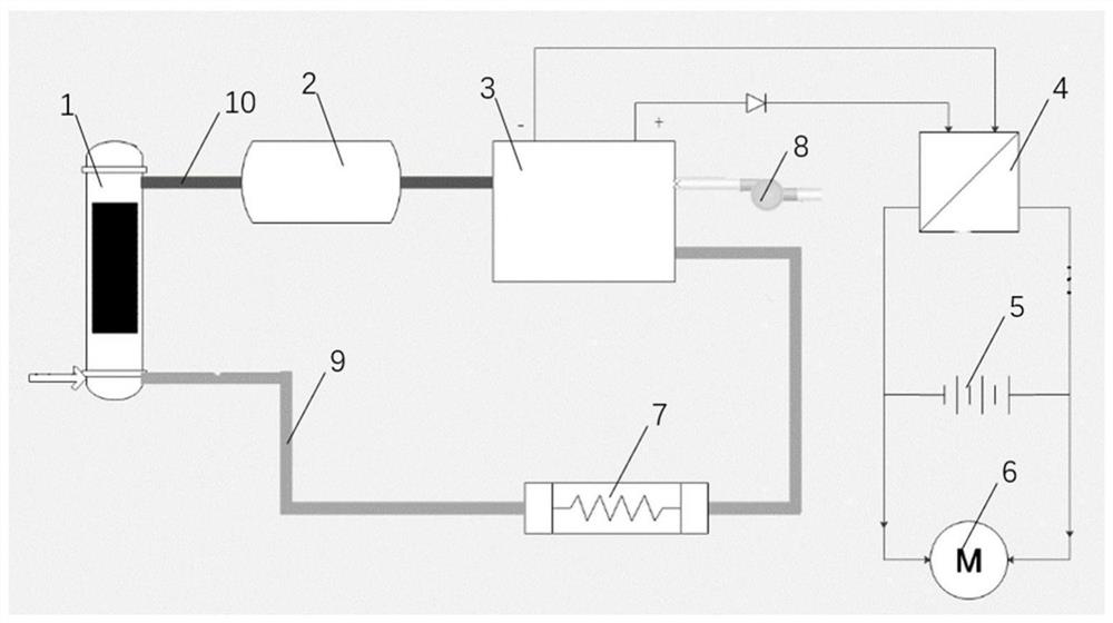
[0033] It includes a reactor 1, a hydrogen storage tank 2, a fuel cell 3, a DC / DC converter 4, a lithium battery 5, a motor 6, a heat exchanger 7 and a water pipeline 9; the upper part of the reactor 1 is provided with an exhaust port, and the The exhaust port 15 delivers hydrogen to the hydrogen storage tank 2 through the hydrogen pipeline 10, and the hydrogen storage tank 2 supplies hydrogen to the fuel cell 3, and the water vapor generated by the fuel cell 3 is converted into liquid water by the heat exchanger 7 and then transported to Reactor 9, the fuel cell 3 is connected to the DC / DC converter 4, the DC / DC converter 4 is connected to the lithium battery 5 and the motor 6, and the DC / DC converter 4 and / or the lithium battery 5 is connected to the motor 6 powered by.

Embodiment 2

[0035] The driving mode adopted is combined drive of fuel cell and storage battery, in which the fuel cell is used as the main power source and the storage battery is used as the auxiliary power source.

[0036] Both the fuel cell and the battery are directly connected to the drive motor, and the fuel cell system and the battery are also connected to each other. Under normal flight conditions, the fuel cell system is used to directly power the motors. When take-off and emergency braking are required, the fuel cell and the storage battery jointly provide electric power to the motor. At the same time, when the power of the battery is low, the fuel cell can be used to charge the battery to ensure that the entire drive system has enough power to meet the flight requirements.

Embodiment 3

[0038] On the basis of embodiment 2,

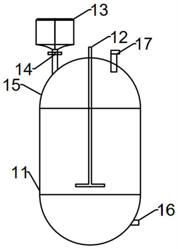
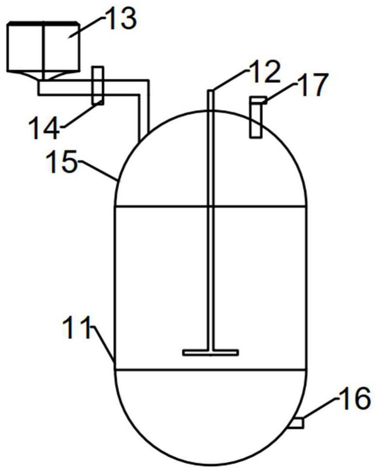
[0039] The magnesium hydride is sent to the reaction kettle filled with water. Among them, magnesium hydride will be made into a volume of about 8~12 mm 3 Small balls (about 47,000) are all stored in the hydrogen storage tank. The inner diameter of the pipeline is 10 mm. A movable piston is set in the horizontal pipeline, which is pushed every 20 seconds to send part of the magnesium hydride beads into the reactor. It is estimated that the transportation of all magnesium hydride will be completed in 2 hours and 30 minutes to ensure that excessive hydrogen will not be generated to cause excessive pressure in the reactor. The hydrogen produced in advance will be stored in hydrogen storage tanks.

[0040] When the reaction starts, the bottom of the kettle is filled with 200 g of low-concentration magnesium chloride solution, the height is about 1 / 3 of the reactor, and the stirring paddle can be covered to ensure that the stirring paddle c...


PUM


Abstract

The present invention relates to a hydrogen fuel cell power system of an unmanned aerial vehicle. The system comprises a reaction kettle, a hydrogen storage tank, a fuel cell, a DC/DC converter, a lithium battery, a motor, a heat exchanger and a water pipeline, an exhaust port is formed in the upper middle portion of the reaction kettle and conveys hydrogen to the hydrogen storage tank through a hydrogen pipeline, the hydrogen storage tank supplies hydrogen to the fuel cell, water vapor generated by the fuel cell is converted into liquid water through the heat exchanger and then conveyed to the reaction kettle, the fuel cell is connected with the DC/DC converter, and the DC/DC converter is connected with the lithium battery and the motor. The fuel cell and/or the lithium battery supplies power to the motor.

Description

technical field [0001] The invention relates to the field of hydrogen power, in particular to a hydrogen fuel cell power system for an unmanned aerial vehicle. Background technique [0002] In recent years, the UAV industry has developed rapidly in both the military and civilian fields. However, the existing UAVs generally have a shortcoming problem, that is, the battery life is short. Ordinary civilian drones generally do not exceed 45 minutes in continuous flight. The small size of civilian drones restricts its own weight from being too large, so there is always a limit to the battery volume. If the battery volume is increased, the energy consumption will increase accordingly. At the same time, with the rapid decarbonization of land transport underway, the fast-growing air transport industry is fast becoming a major source of carbon emissions, so ways must be found to make aviation more sustainable. Under the double consideration of battery life and environmental protect...

Claims


Application Information

Patent Timeline
Patent Type & Authority Applications(China)
IPC IPC(8): H01M8/065H01M8/04029H01M8/04082H01M8/04089B64D27/24C01B3/06
CPCH01M8/065H01M8/04201H01M8/04089H01M8/04029B64D27/24C01B3/065H01M2250/20Y02E60/36Y02E60/50Y02P70/50Y02T90/40
Inventor 吴震付铁峰
Owner 氢源风新动力科技(苏州)有限公司
Why Eureka
Try Eureka