Combined friction clutch brake with low driven system inertia of mechanical press

A technology of friction clutches and mechanical presses, which is applied in the direction of mechanically driven clutches, mutually meshing clutches, clutches, etc., which can solve the problems of physical and mental health injuries of workers, low energy utilization, and poor sensitivity of clutch actions, so as to avoid stuffy cars or Brake failure, improve action sensitivity, brake action sensitive effect

Active Publication Date: 2021-12-03
XI AN JIAOTONG UNIV
View PDF7 Cites 0 Cited by
  • Summary
  • Abstract
  • Description
  • Claims
  • Application Information

AI Technical Summary

Problems solved by technology

[0009] (1) The cylinder that transmits torque when the clutch is engaged will rotate synchronously with the crankshaft, so that the driven system includes the driven part of the cylinder piston, resulting in the moment of inertia J of the driven system c increase, the sensitivity of the clutch action is poor, when the clutch is engaged, the friction work on the surface of the friction material and the moment of inertia J c proportional to such that J c ω m 2 / 2 increases, resulting in severe heat generation of the friction material of the clutch, increased wear of the friction material, and reduced service life
[0010] (2) The driving source of the coupling and braking of the clutch and the brake adopts the driving method of compressed air, while the energy conversion rate of the compressed air generated by the air compressor is low, and the noise of the air compressor itself is large, causing noise pollution in the workshop; In addition, compared with the hydraulic pump system, the air compressor occupies a large area and the pipeline is complicated
[0011] (3) During the engagement and braking process of the clutch and brake, if the driving method of compressible air is used, the clutch engagement process and the brake braking process will be slow, which will easily cause the clutch and brake to be stuffy, or the brakes will fail. failure; and the use of pneumatic methods, resulting in up to 110dB (A) intake and exhaust noise during the working process of the clutch and brake, serious environmental pollution, and serious damage to the physical and mental health of workers
[0012] (4) Because the cylinder of the clutch will rotate with the crankshaft, a rotary joint (swivel joint) must be used to introduce compressed air into the center hole of the crankshaft, and then into the clutch cylinder through the rotary seal, resulting in compressed air transmission Many places need to be sealed during the journey, and holes must be drilled in the middle of the crankshaft, which makes the structure complex, large air leakage, and low energy utilization
[0013] (5) The clutch and brake are placed between the flywheel and the machine body, the heat generated by friction cannot be dissipated in time, and the flywheel must be removed when repairing and disassembling the friction material and replacing the friction material, so the maintenance period is long and maintenance is inconvenient

Method used


Image

  • Combined friction clutch brake with low driven system inertia of mechanical press
  • Combined friction clutch brake with low driven system inertia of mechanical press
  • Combined friction clutch brake with low driven system inertia of mechanical press

Examples


Embodiment Construction

[0036] The present invention will be described in detail below in conjunction with the accompanying drawings and embodiments.

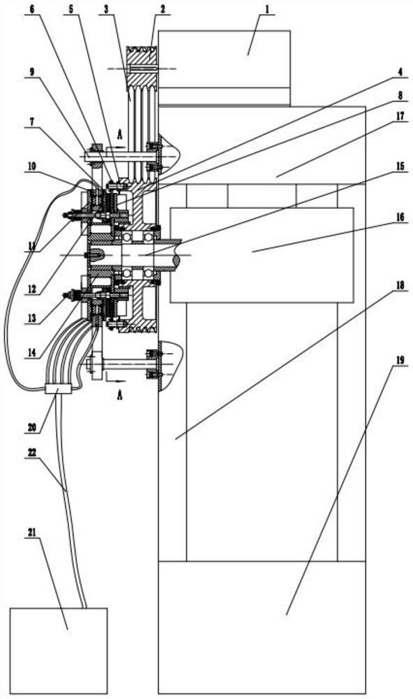
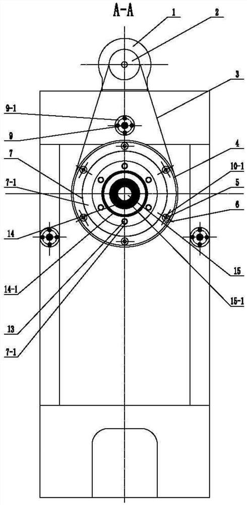
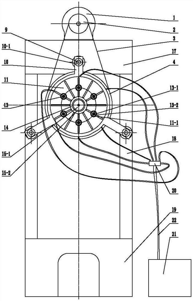
[0037] refer to figure 1 , figure 2 , image 3 , a combined friction clutch brake with low inertia of the driven system of a mechanical press, including a press fuselage connected by an upper beam 17, a column 18, and a base 19. The press fuselage is connected with a crankshaft 15 and its accessories. The transmission system 16, and the hydraulic pipeline system composed of hydraulic valve switch 20, oil pump 21, oil pipe 22, etc.; the friction clutch, friction brake and flywheel 4 form a whole in structure, and are located on the outer side of the press body. The brake is located on the outermost side, the friction clutch is located in the middle, the friction clutch and the friction brake are provided with an interlocking structure, the flywheel 4 is close to the press body; the drive motor 1 is installed on the upper beam 17, and the drive motor...


PUM


Abstract

A combined friction clutch brake with low driven system inertia of a mechanical press comprises a press body. The press body is connected with a transmission system composed of a crankshaft and accessories of the crankshaft. A flywheel and a clutch-brake supporting sleeve are installed on the crankshaft, a friction clutch and a friction brake are connected to the clutch-brake supporting sleeve, the friction clutch and the friction brake are provided with rigid interlocking structures, and the friction clutch and the friction brake are connected with a hydraulic pipeline system. The flywheel is driven by a driving motor to move, the flywheel can independently rotate and move on the crankshaft, and the movement and stop of the crankshaft are controlled by using a friction clutch brake. The crankshaft does not need to be machined with a center air hole, and the combined friction clutch brake has the advantages of being low in driven system rotational inertia, small in friction heating amount, good in heat dissipation effect, high in energy utilization rate, compact in structure, coordinated in action, easy and convenient to operate, convenient to maintain, low in noise pollution and the like.

Description

technical field [0001] The invention belongs to the technical field of mechanical presses for forging equipment, and in particular relates to a combined friction clutch brake with low inertia of the driven system of the mechanical press. Background technique [0002] The mechanical press is often subjected to short-term peak loads, and it is often necessary to frequently move and stop the slider during the forging work. Therefore, the transmission system of the mechanical press often has a flywheel with a large inertia, and the main energy of the forging work is Output from the rotational kinetic energy of the flywheel. Based on the main reasons of the above two aspects, as well as the convenience for operators to debug molds and ensure the safety of workers, mechanical presses are basically equipped with clutches and brakes, the heart parts of mechanical presses, to control the movement of the working mechanism of the press. and stop. The reliability, safety and convenien...

Claims


Application Information

Patent Timeline
Patent Type & Authority Applications(China)
IPC IPC(8): F16D55/24F16D65/097F16D65/18F16D11/16F16F15/30F16D121/06
CPCF16D55/24F16D65/0972F16D65/18F16D11/16F16F15/30F16D2121/06F16D67/04F16D65/123F16D2065/1364F16D2065/1372B30B15/10B30B15/12F16D25/082
Inventor 赵升吨高景洲杜威蒋飞郑臻皓
Owner XI AN JIAOTONG UNIV
Why Eureka
Try Eureka