Method and device for automatically generating groove cutting track, computer equipment and medium

A technology of automatic generation and trajectory, applied in the field of image recognition, to achieve the effect of improving the overall operation efficiency and reducing the difficulty of manual operation

Active Publication Date: 2021-12-07
SEIZET TECH SHEN ZHEN CO LTD
View PDF6 Cites 4 Cited by
  • Summary
  • Abstract
  • Description
  • Claims
  • Application Information

AI Technical Summary

Problems solved by technology

[0006] The object of the present invention is to propose a method for automatically generating robot trajectory for steel plate cutting and beveling, so as to solve the problems existing in the prior art

Method used


Image

  • Method and device for automatically generating groove cutting track, computer equipment and medium
  • Method and device for automatically generating groove cutting track, computer equipment and medium
  • Method and device for automatically generating groove cutting track, computer equipment and medium

Examples


Embodiment 1

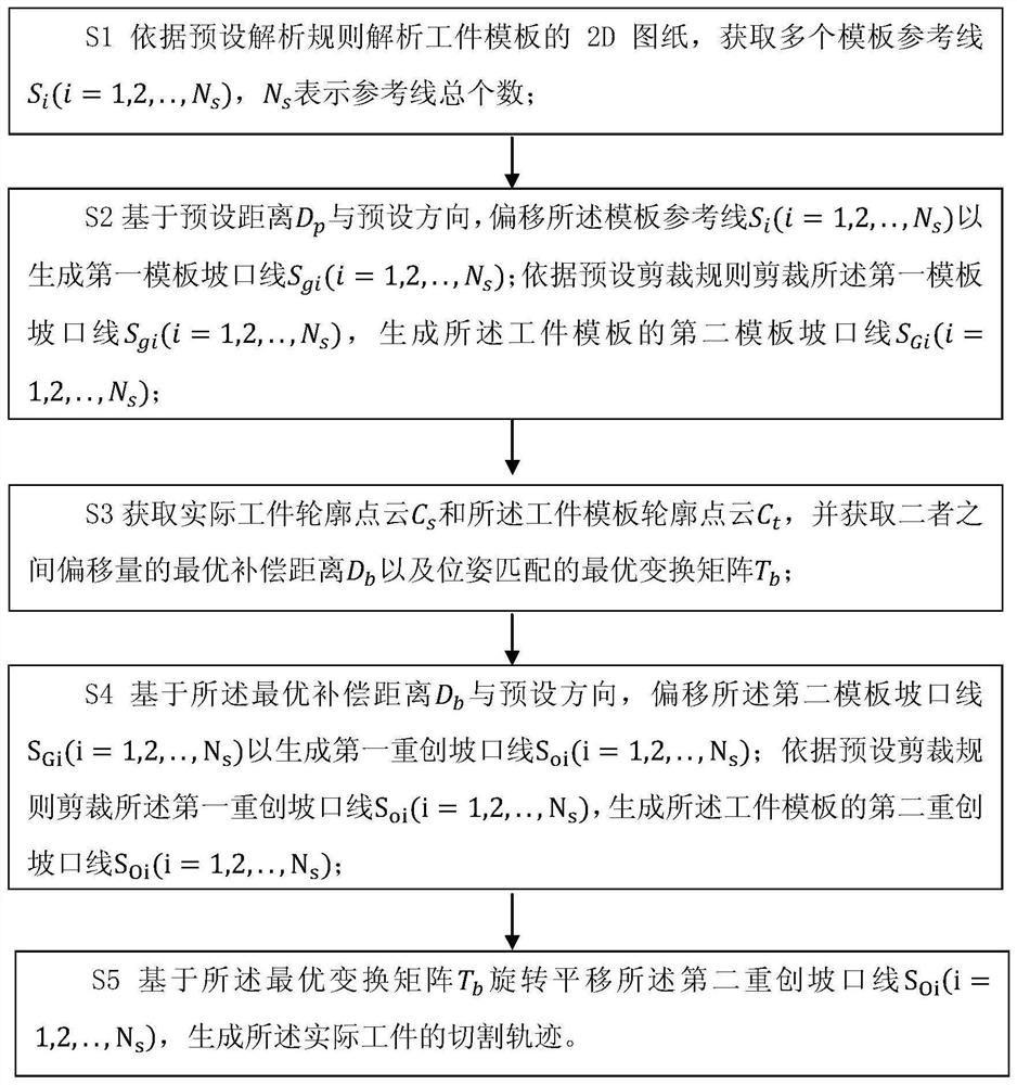
[0046] Such as figure 1 As shown, the present invention provides a method for automatically generating groove cutting tracks, comprising the following steps:

[0047] S1 Analyze the 2D drawing of the workpiece template according to the preset analysis rules, and obtain multiple template reference lines S i (i=1, 2, . . . , N s ), N s Indicates the total number of reference lines;

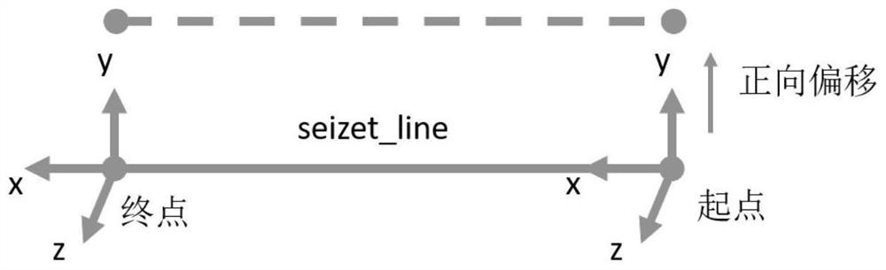
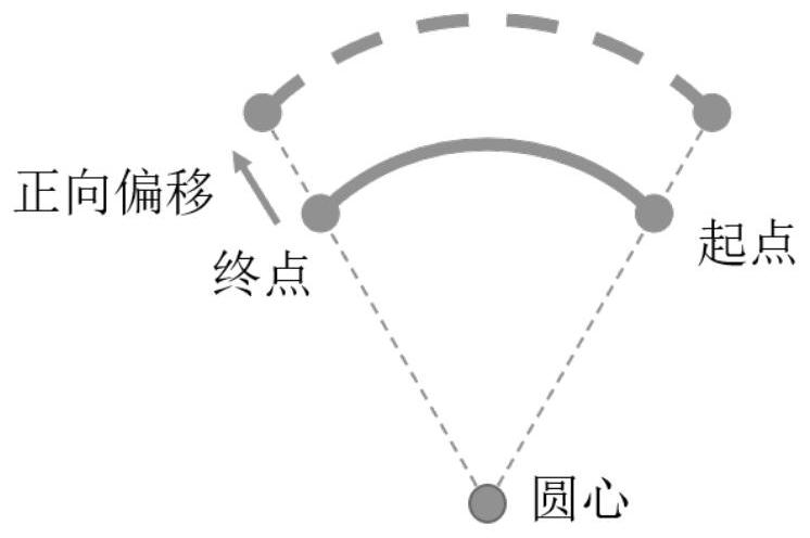
[0048] S2 based on preset distance D p With a preset orientation, offset the template reference line S i (i=1, 2, . . . , N s ) to generate the first template groove line S gi (i=1, 2, . . . , N s ); according to the preset cutting rules, the groove line S of the first template is cut gi (i=1, 2, . . . , N s ), generate the second template groove line S of the workpiece template Gi (i=1, 2, . . . , N s );

[0049] S3 obtains the actual workpiece contour point cloud C s and the workpiece template contour point cloud C t , and obtain the optimal compensation distance D of the offset betw...

Embodiment 2

[0311] Such as Figure 13 As shown, the present invention also discloses a device 10 for automatically generating groove cutting tracks, including:

[0312] The reference line acquisition module 11 is used to analyze the 2D drawing of the workpiece template according to the preset analysis rules, and obtain multiple template reference lines S i (i=1, 2, . . . , N s ), N s Indicates the total number of reference lines;

[0313] The first template groove line acquisition module 12 is used for based on the preset distance D p With the preset orientation, offset the template reference line S i (i=1, 2, . . . , N s ) to generate the first template groove line S gi (i=1, 2, . . . , N s );

[0314] A trimming module 13, configured to trim the first heavily wounded groove line S according to preset trimming rules oi (i=1, 2, . . . , N s ), generate the second heavy-wound groove line S of the workpiece template Oi (i=1, 2, . . . , N s ), and for cutting the first template g...

Embodiment 3

[0476] Figure 14Shown is a schematic structural diagram of a computer device provided by an embodiment of the present invention, such as a smart phone, a tablet computer, a notebook computer, a desktop computer, a rack server, a blade server, a tower server or a cabinet server that can execute programs (including independent servers, or server clusters composed of multiple servers), etc. The computer device 20 in this embodiment at least includes but is not limited to: a memory 21 and a processor 22 that can be communicated with each other through a system bus, as shown in FIG. 14 . It should be pointed out that, Figure 14 Only computer device 20 is shown having components 21-22, but it should be understood that implementing all of the illustrated components is not a requirement and that more or fewer components may instead be implemented.

[0477] In this embodiment, the memory 21 (that is, a readable storage medium) includes a flash memory, a hard disk, a multimedia card...


PUM


Abstract

The invention provides a method for automatically generating a groove cutting track. The method for automatically generating the groove cutting track comprises the following steps that a 2D drawing of a workpiece template is analyzed to obtain a plurality of template reference lines S (i = 1, 2,..., N); based on the preset distance D

and the preset direction, the template reference lines are shifted to generate a first template groove line S<gi> (i = 1, 2,..., N); the first template groove line S<gi> (i = 1, 2,..., N) is cut to generate a second template groove line S<Gi> (i = 1, 2,..., N); an actual workpiece contour point cloud C and a workpiece template contour point cloud C<t> are acquired, and an optimal compensation distance D of an offset between the two contour point clouds and an optimal transformation matrix T of pose matching are acquired; based on the D and a preset direction, the second template groove line S<Gi> (i = 1, 2,..., N) is shifted to generate a first serious groove line S<oi> (i = 1, 2,..., N); the first serious groove line S<oi> (i = 1, 2,..., N) is cut, and a second serious groove line S<oi> (i = 1, 2,..., N) of the workpiece template is generated; and the second serious groove line S<oi> (i = 1, 2,..., N) is rotated and translated based on the T, a cutting track of an actual workpiece is generated, and the cutting track of the actual workpiece can be automatically obtained only through one-time photographing. The workpiece machining errors and feeding placement errors can be adopted, and the manual operation difficulty and the feeding and feeding requirements are lowered.

Description

technical field [0001] The invention belongs to the field of image recognition, and in particular relates to a method, device, computer equipment and storage medium for automatically generating groove track. Background technique [0002] Steel plate groove cutting is the previous process of welding, and the accuracy and consistency of the groove are the key factors affecting the welding quality. For workpieces with simple contours, such as straight-edged steel plates, traditional manual beveling or CNC beveling machines are still competent. However, there are many arcs and curves in the contours of steel plate workpieces in modern industry, and there are many types and new additions. It is difficult to guarantee the accuracy and consistency of the bevel by the traditional bevel cutting method. With the increasing application of industrial robots, the cutting and beveling method of robots carrying flame cutting guns or plasma cutting guns has gradually attracted the attentio...

Claims


Application Information

Patent Timeline
Patent Type & Authority Applications(China)
IPC IPC(8): B23K7/00B23K7/10B23K10/00G06F30/17
CPCB23K7/00B23K7/10B23K10/00G06F30/17
Inventor 田希文高磊
Owner SEIZET TECH SHEN ZHEN CO LTD
Why Eureka
Try Eureka