Three-dimensional steel fiber, manufacturing mold and method and concrete applying three-dimensional steel fiber

A steel fiber, three-dimensional technology, which is applied in the field of three-dimensional steel fibers, manufacturing molds and methods, and concrete fields using three-dimensional steel fibers, can solve the problem of limited fiber bridging effect, destroying the shape of three-dimensional steel fibers, and not much utilization and research and development of three-dimensional steel fibers. and other problems, to achieve the effect of improving the ability to resist elastic shock waves, reducing the risk of cracking, and improving mechanical properties

Pending Publication Date: 2021-12-07
ZHEJIANG SCI-TECH UNIV
View PDF5 Cites 0 Cited by
  • Summary
  • Abstract
  • Description
  • Claims
  • Application Information

AI Technical Summary

Problems solved by technology

[0003] Existing different types of steel fibers belong to "one-dimensional" size fibers because the size in one direction is much larger than other directions, and a specific feeding process is required to play a better "bridging" role, and the distribution in the mold It only presents a two-dimensional distribution, and it cannot effectively resist the effect of elastic shock waves in the third direction. To a certain extent, the advantages of SIFCON have not been fully utilized in protection and other projects.
Secondly, although there are some three-dimensional steel fibers today, they are not used in SIFCON, only in steel fiber concrete, but this also creates another problem. The steel fiber concrete will destroy the three-dimensional steel fiber during the mixing process. The shape of the three-dimensional steel fiber cannot give full play to the advantages of three-dimensional steel fiber, so the utilization and development of three-dimensional steel fiber is not much, which also limits the development of SIFCON to a certain extent
[0004] Chinese patent CN201420291784.3 discloses a three-dimensional steel fiber, which bends the steel fiber multiple times, only the second section and the first section are not in the same plane after bending, and the end hook is to increase the end anchorage, but Since the length of the straight section accounts for 2 / 3 of the total length of the steel fiber, the projection length of the fiber in other directions is much smaller than that of the straight section, and the bridging effect between the fibers is limited

Method used


Image

  • Three-dimensional steel fiber, manufacturing mold and method and concrete applying three-dimensional steel fiber
  • Three-dimensional steel fiber, manufacturing mold and method and concrete applying three-dimensional steel fiber
  • Three-dimensional steel fiber, manufacturing mold and method and concrete applying three-dimensional steel fiber

Examples


Embodiment 1

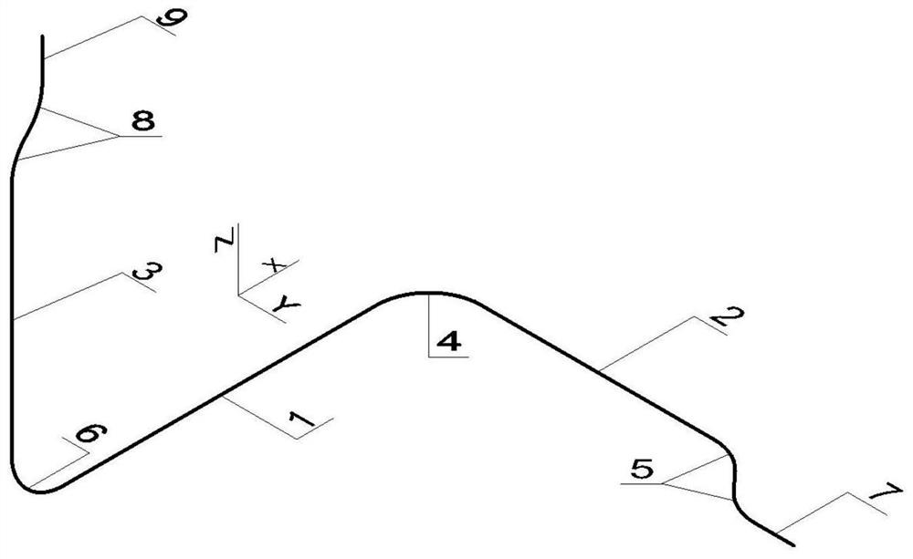
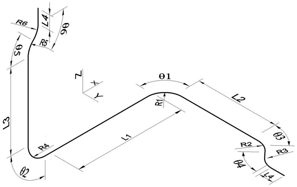
[0064] The nominal tensile strength is not less than 1100MPa, a steel wire having a diameter of 0.55 mm and a length of 44 mm, wherein it is prepared according to the above steps, wherein the length L1 of the line segment 1 is 12.0 mm, and the length L2 of the line segment 2 is 6.0 mm. The length L3 of the linear segment 3 is 6.0 mm, the radius r1 and R4 of the arc segments 4 and 6 are 4.0 mm, the angles θ1 and θ2 are π / 2, and the radius of the two anti-direction small arc of the large circular arc segment 5. And R3 is 2.0mm, the angles θ3 and θ4 are π / 4, and the radius R5 and R6 of the two anti-direction small arcs of the large circular arc section 8 are 2.0 mm, angles θ5 and θ6 are π / 4, two straight segments. The length L4 of 7 and 9 is 2.0mm, and the steel fiber has a long diameter ratio of 80.

Embodiment 2

[0066] The nominal tensile strength is not less than 1100 MPa, a steel wire having a diameter of 0.55 mm and a length of 44 mm, wherein it is prepared according to the above steps, wherein the length L1 of the line segment 1 is 9.0 mm, and the length L2 of the line segment 2 is 9.0 mm. The length L3 of the linear segment 3 is 9.0 mm, the radius R1 and R4 of the arc segments 4 and 6 are 2.5 mm, angles θ1 and θ2 are π / 2, and the radius R2 of the two anti-directional arcs of the large circular arc segment 5. And R3 is 2.0mm, the angles θ3 and θ4 are π / 4, and the radius R5 and R6 of the two anti-direction small arcs of the large circular arc section 8 are 2.0 mm, angles θ5 and θ6 are π / 4, two straight segments. The length L4 of 7 and 9 is 1.5 mm, and the steel fiber has a long diameter ratio of 80.

Embodiment 3

[0068] The nominal tensile strength is not less than 1100 MPa, a steel wire having a diameter of 0.55 mm and a length of 36 mm, wherein it is prepared in the above steps, wherein the length L1 of the line segment 1 is 7.0 mm, and the length L2 of the line segment 2 is 7.0 mm. The length L3 of the linear segment 3 is 7.0 mm, the radius R1 and R4 of the arc sections 4 and 6 are 2.0 mm, the angles θ1 and θ2 are π / 2, and the radius R2 of the two anti-directional arcs of the large circular arc segment 5. And R3 is 2.0 mm, 1.5 mm, angle θ3 and θ4 are π / 4, and the radii R5 and R6 of the two anti-direction small arcs of the large circular arc section 8 are 2.0 mm, 1.5 mm, angle θ5 and θ6. π / 4, the length L4 of the two linear sections 7 and 9 is 1.5 mm, and the steel fiber has a long diameter ratio of 65.


PUM

PropertyMeasurementUnit
tensile strengthaaaaaaaaaa
diameteraaaaaaaaaa
lengthaaaaaaaaaa

Abstract

The invention provides a three-dimensional steel fiber which is characterized in that the three-dimensional steel fiber is composed of a plurality of arc sections and linear sections, the linear sections in the X-axis direction are connected with the linear sections in the Y-axis direction and the linear sections in the Z-axis direction through the two arc sections respectively, and a main body part is formed. In order to improve anchoring of the fiber in the base body, anchoring sections can be arranged at the two ends of the fiber, each anchoring section can be composed of one or more continuously-arranged end hooks, and each end hook is composed of one large arc section and one linear section. The SIFCON is a steel fiber with a three-dimensional size, three-dimensional distribution can be effectively formed in a mold no matter how a feeding process is adopted, so that the prepared SIFCON can play a good resisting role no matter in which direction the SIFCON is stretched or compressed, the bonding strength with a base body is obviously improved, and the service life of the SIFCON is prolonged. The mechanical property and the elastic shock wave resistance are greatly improved.

Description

Technical field [0001] The present invention relates to fiber-irrigated concrete technology, particularly relates to a three-dimensional steel fiber concrete, and for producing a mold and Applications of 3D steel fibers. Background technique [0002] And sub-irrigated fiber concrete (Slurry infiltrated fiber concrete, referred SIFCON) is a special type of fiber reinforced concrete, with a separate fibrous matrix, confer important tensile properties of composite matrix, and due to its high fiber content, also has a unique ductility and energy absorption properties. Although SIFCON because of the heavy steel fibers, resulting in a high cost, but it has been more widely used around the world, especially in the blast and impact structures. In general, conventional fiber reinforced concrete comprising from 1 to 2% by volume of the fibers, if more than 2% by volume of the fibers may cause the fibers agglomerate, but reduces the properties of the material, and can be done SIFCON contain...

Claims


Application Information

Patent Timeline
Patent Type & Authority Applications(China)
IPC IPC(8): C04B14/48C04B28/00B21F1/00B21F23/00
CPCC04B14/48C04B28/00B21F1/00B21F23/00C04B18/08C04B18/146C04B14/06C04B2103/302
Inventor 李贺东李亚彪王敏嘉潘云锋
Owner ZHEJIANG SCI-TECH UNIV
Why Eureka
Try Eureka