System and method for testing alkali metal atom number density spatial distribution uniformity of atom magnetometer

A technology of atomic magnetic intensity and spatial distribution, which is applied to the size/direction of the magnetic field, the use of magneto-optical equipment for magnetic field measurement, measurement devices, etc. Uneven distribution and other problems, to achieve the effect of suppressing common mode interference, easy implementation and simple operation

Active Publication Date: 2021-12-10
ZHEJIANG LAB
View PDF6 Cites 3 Cited by
  • Summary
  • Abstract
  • Description
  • Claims
  • Application Information

AI Technical Summary

Problems solved by technology

If the temperature distribution of the heating oven is uneven, it will lead to uneven distribution of atomic number density, and the common mode noise of gradient differential detection will become larger
[0003] At present, the commonly used methods for testing the atomic number density include the Faraday optical rotation effect method, the magnetic resonance linewidth method, and the spectral absorption method: the Faraday optical rotation angle method needs to apply a large magnetic field, which cannot make the magnetometer work without spin exchange. In the relaxed state; the magnetic resonance linewidth method requires very low atomic polarizability, otherwise the magnetic resonance linewidth is also affected by the spin destruction rate
The spectral absorption method is more commonly used, but it can only measure the overall value of the atomic number density of the gas cell, and cannot measure the spatial distribution of the atomic number density
Therefore it is not possible to analyze the homogeneity

Method used


Image

  • System and method for testing alkali metal atom number density spatial distribution uniformity of atom magnetometer
  • System and method for testing alkali metal atom number density spatial distribution uniformity of atom magnetometer
  • System and method for testing alkali metal atom number density spatial distribution uniformity of atom magnetometer

Examples


Embodiment Construction

[0021] The present invention will be further described below through the accompanying drawings and specific embodiments.

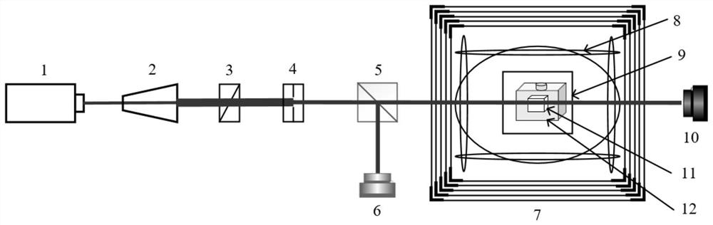
[0022] Such as figure 1 As shown, the present invention proposes a test system for the uniformity of the spatial distribution of the alkali metal atomic number density of an atomic magnetometer, including a detection light laser 1, a laser beam expander 2, and a polarizer 3 arranged in sequence according to the direction in which the detection light advances , diaphragm 4, beam splitting prism 5, alkali metal atom gas chamber 11, first beam profile camera 10, described alkali metal atom gas chamber 11 is coated with oven 12, vacuum cavity 9, magnetic compensation coil in sequence from inside to outside 8. Magnetic shielding system 7; the beam splitting prism 5 divides the detection light into two beams of refracted light, one beam of refracted light enters the first beam profile camera 10 after passing through the alkali metal atom gas chamber 11, and the ...


PUM


Abstract

The invention discloses a system and a method for testing alkali metal atom number density spatial distribution uniformity of an atom magnetometer. The system comprises a detection laser, a laser beam expanding system, a polarization element, a magnetic shielding system, an alkali metal atom gas chamber, a light beam contour camera, a beam splitter prism and the like which are sequentially arranged in a light advancing direction. The method is based on an optical absorption principle, light intensity attenuation of linear polarized light before and after passing through an alkali metal air chamber is tested by using a light beam profile camera with a pixel at a um level, a two-dimensional distribution matrix of atomic number density in space is calculated, and the uniformity of atomic number density distribution is analyzed by using a discrete coefficient. The system is simple to operate, easy to implement and extremely high in resolution ratio, direct measurement can be carried out on the basis of not changing the optical path of the atom magnetometer, the uniformity of the atomic number density in spatial distribution can be tested with high precision, the measurement sensitivity can be improved, and particularly the common-mode interference of a multi-channel differential magnetometer can be inhibited.

Description

technical field [0001] The invention belongs to the technical field of precision measurement, in particular to a test system and method for the uniformity of spatial distribution of alkali metal atomic number density of an atomic magnetometer. Background technique [0002] The alkali metal atomic magnetometer without spin exchange relaxation effect has extremely high magnetic field measurement sensitivity, and has been widely used in basic physics research, biomedicine, geomagnetic detection and other fields. The alkali metal atomic gas chamber is the core device of the atomic magnetometer. It needs to be heated to increase the atomic number density of the alkali metal vapor during use. This is because the atomic number density is proportional to the sum of the strength of the output signal and the square of the basic sensitivity Inversely proportional, so the greater the atomic number density, the stronger the output signal, and the smaller the minimum magnetic field that c...

Claims


Application Information

Patent Timeline
Patent Type & Authority Applications(China)
IPC IPC(8): G01N21/84G01N21/01G01R33/032
CPCG01N21/84G01N21/01G01R33/032
Inventor 郭强李学文张宁陆吉玺王子轩
Owner ZHEJIANG LAB
Why Eureka
Try Eureka